Surface defect detection method and device for injection molding part, equipment and storage medium

A defect detection and injection molding technology, applied in the field of computer vision, can solve problems such as deviation, measurement result change, false detection, etc., and achieve the effects of reducing enterprise training and management costs, fast and accurate detection, and solving detection errors

Inactive Publication Date: 2019-09-20
HANGZHOU WEIMING XINKE TECH CO LTD +1
View PDF2 Cites 7 Cited by
  • Summary
  • Abstract
  • Description
  • Claims
  • Application Information

AI Technical Summary

Problems solved by technology

[0003] At present, most enterprises use manual visual inspection to find defects on the surface of injection molded parts, but manual visual inspection often produces deviations due to the influence of employees' seriousness, mood, fatigue and other factors, resulting in missed and false detections situation occurs
Some enterprises have begun to try to find defects on the surface of injection molded parts by using industrial cameras to take pictures and measure specific defect indicators in the image, such as the length of scratches, the area of ​​notches, and the color of the surface; however, in this method, when the When the position of the injection molded part on the production line deviates, or the external light changes, the measurement results will also change accordingly; at the same time, when a new defect finding requirement arises, the staff needs to redesign the detection plan for the new defect, and Repeated measurement experiments are time-consuming and labor-intensive

Method used


Image

  • Surface defect detection method and device for injection molding part, equipment and storage medium
  • Surface defect detection method and device for injection molding part, equipment and storage medium
  • Surface defect detection method and device for injection molding part, equipment and storage medium

Examples


Embodiment Construction

[0048] Exemplary embodiments of the present disclosure will be described in more detail below with reference to the accompanying drawings. Although exemplary embodiments of the present disclosure are shown in the drawings, it should be understood that the present disclosure may be embodied in various forms and should not be limited by the embodiments set forth herein. Rather, these embodiments are provided for more thorough understanding of the present disclosure and to fully convey the scope of the present disclosure to those skilled in the art.

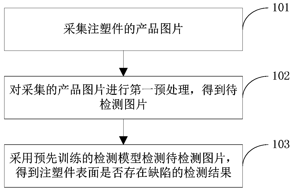
[0049] attached figure 1 A flow chart of a surface defect detection method for injection molded parts provided by some embodiments of the present application, such as figure 1 As shown, the defect detection methods of injection molded parts include:

[0050] Step 101: collecting product pictures of injection molded parts;

[0051] Specifically, the product pictures of injection molded parts are taken by computer vision equipment,...


PUM


Abstract

The invention provides a surface defect detection method and device for an injection molding part, equipment and a storage medium, and relates to the technical field of computer vision. The method comprises the following steps: acquiring a product picture of an injection molding part; carrying out first preprocessing on the product picture to obtain a to-be-detected picture; and detecting the obtained to-be-detected picture by adopting a pre-trained detection model to obtain a detection result about whether the surface of the injection molding part has defects or not. According to the technical scheme, the computer vision and the neural network are combined in advance to train the detection model, and the detection model is adopted to detect the to-be-detected picture, so that whether defects exist on the surface of the injection molding part or not is quickly and accurately detected. The problem of detection errors caused by external factors such as emotion changes of detection personnel in current manual visual inspection solved, and the problems that a traditional solution is low in compatibility and cannot quickly adapt to new requirements are solved. The enterprise training and management cost is reduced, and the problem that defective goods flow into the market to cause loss to enterprises is effectively avoided.

Description

technical field [0001] The present application relates to the technical field of computer vision, and in particular to a method, device, equipment and storage medium for detecting surface defects of injection molded parts. Background technique [0002] All kinds of injection molding products produced by injection molding machines are collectively called injection molded parts. In the production process of injection molded parts, surface defects, such as lack of material (missing edge) often occur due to reasons such as raw material selection, temperature setting, process design, and human error. small pieces), dents, scratches, flow marks (ripples on the surface), etc. [0003] At present, most enterprises use manual visual inspection to find defects on the surface of injection molded parts, but manual visual inspection often produces deviations due to the influence of employees' seriousness, mood, fatigue and other factors, resulting in missed and false detections situatio...

Claims


Application Information

Patent Timeline
IPC IPC(8): G06T7/00G06T7/90G01N21/88
CPCG06T7/0008G06T7/90G01N21/8851G01N2021/8893G06T2207/10004G06T2207/20081G06T2207/20084G06T2207/30164
Inventor 陈曦龚小龙罗天成麻志毅
Owner HANGZHOU WEIMING XINKE TECH CO LTD
Why Eureka
Try Eureka