
Camera lens protection device

A protection device and lens technology, applied in the field of cameras, can solve the problems of impact analysis and processing, blurred lens, poor image quality, etc., and achieve the effect of improving camera quality.

Inactive Publication Date: 2019-09-20
阚智博
View PDF13 Cites 2 Cited by
  • Summary
  • Abstract
  • Description
  • Claims
  • Application Information

AI Technical Summary

Problems solved by technology

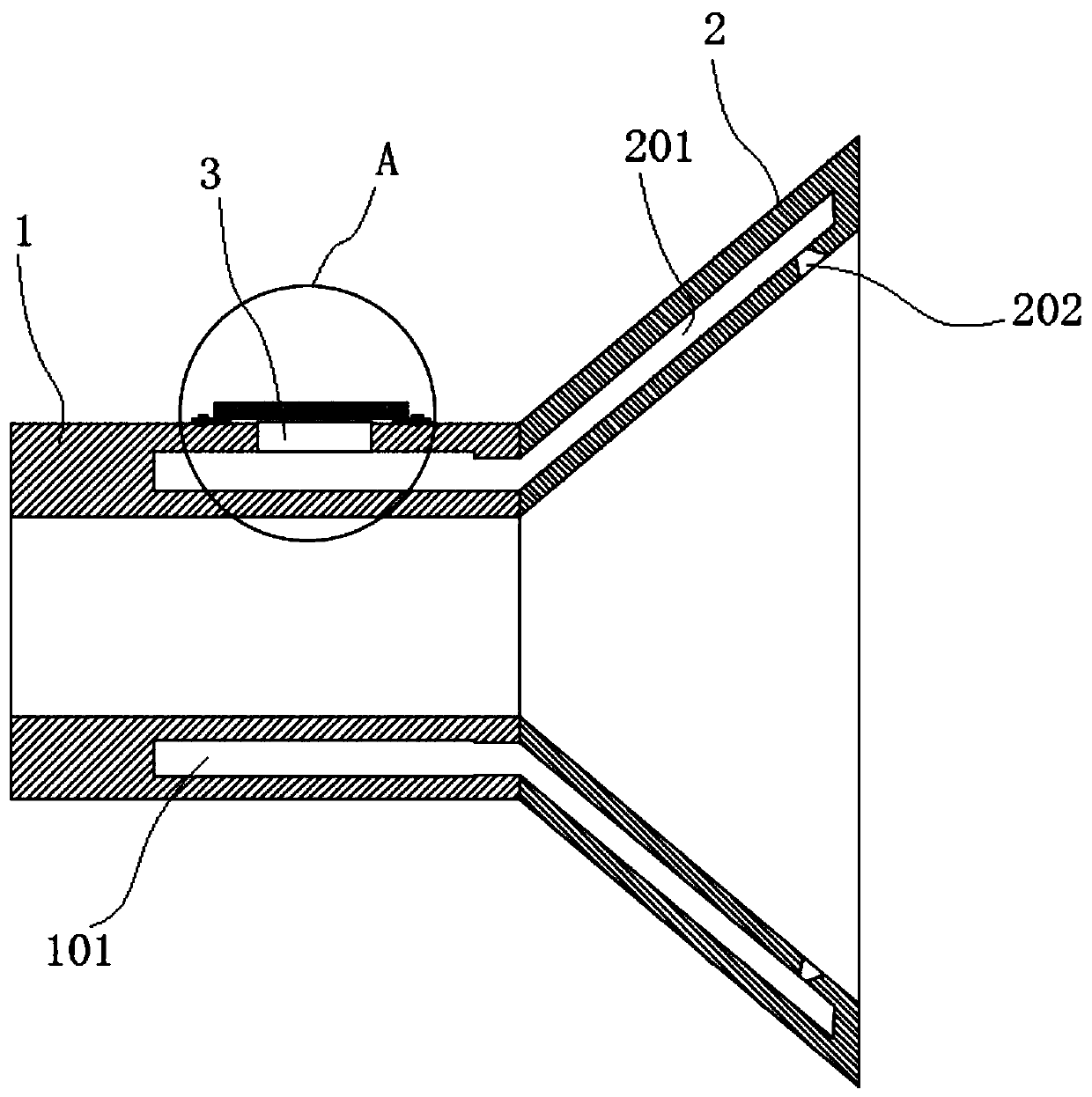
[0003] The purpose of the present invention is to provide a camera lens protection device, by forming an airflow protection zone in front of the camera lens to prevent the dust in the environment from falling on the lens and causing the lens to be blurred, which solves the problem that the existing dust is easy to blur the lens of the camera It is not clear, which leads to the deterioration of the quality of the collected images and affects the later analysis and processing.

Method used


Image

  • Camera lens protection device
  • Camera lens protection device

Examples


Embodiment Construction

[0021] The following will clearly and completely describe the technical solutions in the embodiments of the present invention with reference to the accompanying drawings in the embodiments of the present invention. Obviously, the described embodiments are only some, not all, embodiments of the present invention. Based on the embodiments of the present invention, all other embodiments obtained by persons of ordinary skill in the art without creative efforts fall within the protection scope of the present invention.

[0022] In the description of the present invention, it should be understood that the terms "one end", "diameter", "lower", "upper", "inner side wall", "in the annular direction", "inner", "circumferential direction" etc. Indicating orientation or positional relationship is only for the convenience of describing the present invention and simplifying the description, and does not indicate or imply that the components or elements referred to must have a specific orient...


PUM


Abstract

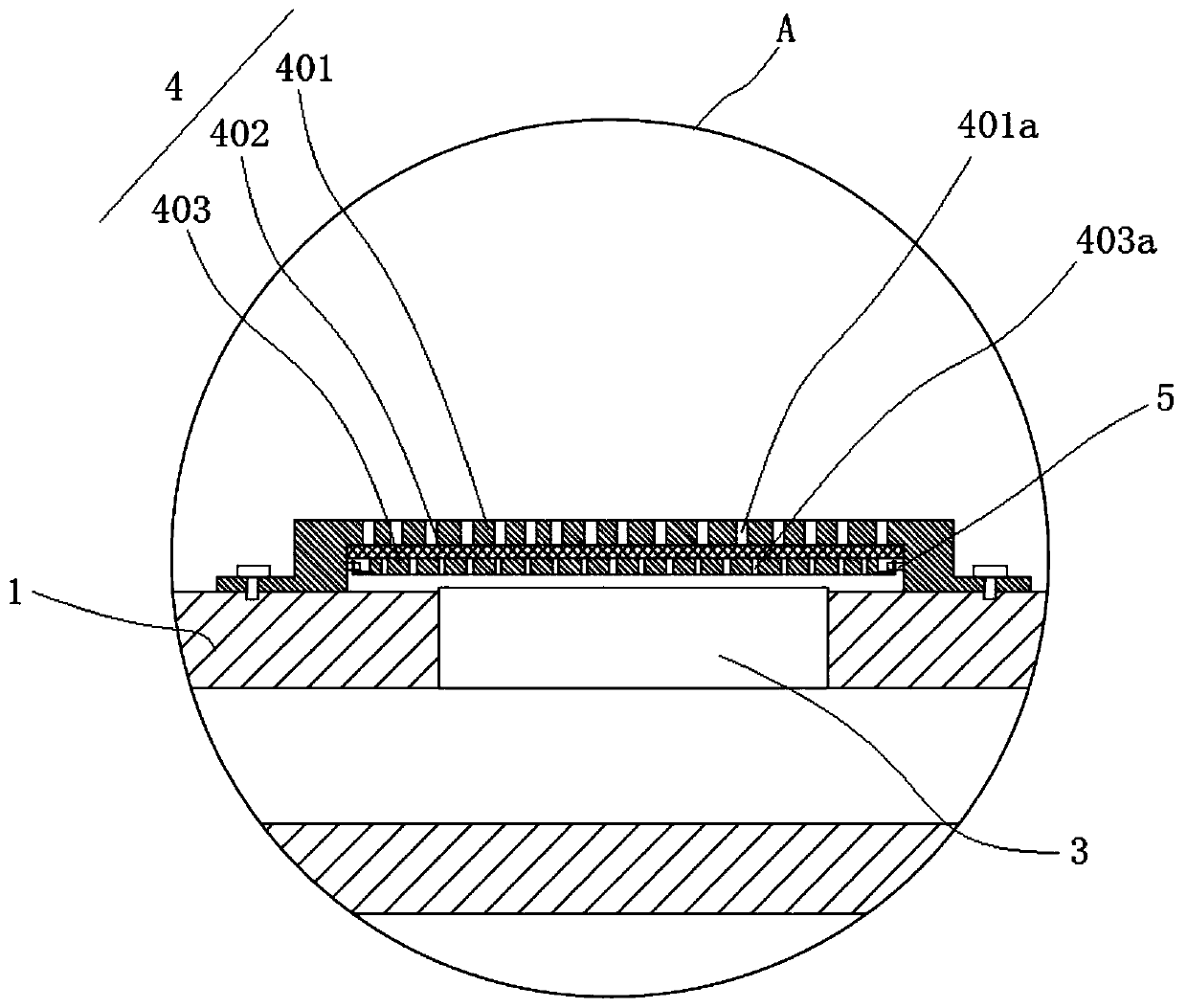
The invention discloses a camera lens protection device, and relates to the technical field of cameras. The device comprises a first connecting cylinder and a second connecting cylinder; the first connecting cylinder is arranged on a camera lens in a sleeving mode; the second connecting cylinder is fixedly mounted at one end of the first connecting cylinder; the diameter of the second connecting cylinder is gradually increased in a direction away from the first connecting cylinder in a trumpet shape; a first cavity is formed in the first connecting cylinder in the circumferential direction; an opening communicating with the first cavity is formed in the outer wall of the first connecting cylinder; the opening is provided with a micro exhaust fan; the opening is further provided with a filter cover; the filter cover covers the micro exhaust fan; the second connecting cylinder is provided with a second cavity in the circumferential direction; the second cavity communicates with the first cavity; and a plurality of exhaust holes communicating with the second cavity are formed in the inner side wall of the second connecting cylinder in the annular direction. According to the device, an airflow protection area is formed in front of the camera lens, so that dust in an environment is prevented from falling onto the camera lens, and the camera shooting quality of the camera is improved.

Description

technical field [0001] The invention belongs to the technical field of cameras, in particular to a camera lens protection device. Background technique [0002] On the factory production line, industrial cameras are usually installed above the conveyor belt to collect images of items on the conveyor belt. The collected images are analyzed and processed. The environment in the factory directly affects the working status of the camera, which affects the quality of the image. However, the vast majority of factories have a lot of dust, which can easily blur the lens of the camera, resulting in the deterioration of the quality of the collected images and affecting the later analysis and processing. Therefore design the protection of a kind of camera lens to appear very necessary. Contents of the invention [0003] The purpose of the present invention is to provide a camera lens protection device, by forming an airflow protection zone in front of the camera lens to prevent the d...

Claims


Application Information

Patent Timeline
IPC IPC(8): G03B17/02B01D46/00
CPCG03B17/02B01D46/0004B01D2258/06
Inventor 阚智博
Owner 阚智博
Learn More