Photoelectric encoder

A photoelectric encoder and code disc technology, applied in the field of photoelectric encoders, can solve the problems of easy fixation, high cost and large volume, and achieve the effects of small size, reduced thickness and cost saving

Pending Publication Date: 2019-09-20
DORNA TECH
View PDF0 Cites 1 Cited by
  • Summary
  • Abstract
  • Description
  • Claims
  • Application Information

AI Technical Summary

Problems solved by technology

One of the core problems of the incremental photoelectric encoder is to accurately ensure the air gap between the code disc and the photoelectric conversion chip on the circuit board. The integrated photoelectric encoder is the mainstream product in the servo market at present. For the integrated encoder Generally speaking, the upper and lower bearings are required to install the rotating shaft inside, so that the rotating shaft can rotate stably in the photoelectric encoder. The arrangement of the two bearings makes the overall shafting size of the photoelectric encoder easy to be fixed, resulting in its existence such as large volume, cost advanced defects

Method used


Image

  • Photoelectric encoder
  • Photoelectric encoder
  • Photoelectric encoder

Examples


Embodiment Construction

[0015] In order to enable those skilled in the art to better understand the technical solutions of the present invention, the present invention will be further described in detail below in conjunction with the accompanying drawings and preferred embodiments.

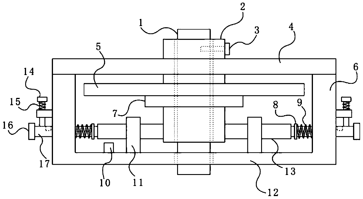
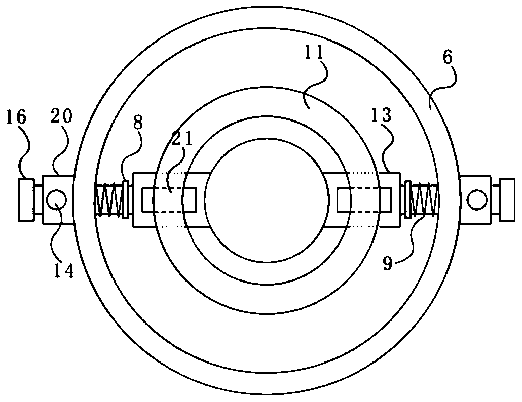
[0016] As shown in the figure, the present invention includes a circuit board 4, a rotating shaft 2 rotatably connected to the circuit board 4, a code disc 5 affixed to the rotating shaft 2, and a base provided with a light-emitting tube 10. The circuit board 4, the rotating shaft 2. Both the code disc 5 and the middle part of the base are provided with shaft passages, and the middle part of the rotating shaft 2 protrudes outward to form a connecting ring rib 7, and the connecting ring rib 7 is fixedly connected with the code disc 5 upward, and the main shaft 1 of the motor to be tested is Through the passage of the rotating shaft, and connected with the rotating shaft 2 through the locking bolt 3, it is characterized in ...


PUM


Abstract

The invention relates to a photoelectric encoder. The photoelectric encoder comprises a circuit board, a rotating shaft, a code disc and a base, wherein the base comprises a bottom plate and a supporting plate; fixing components are symmetrically arranged on two sides of the annular supporting plate; each fixing component comprises a fixing plate, a driving rod, a first spring, a first handheld block and a locking part; each driving rod penetrates the annular supporting plate and is fixedly connected with the fixing plate; the first spring sleeves the middle portion of the driving rod; the two fixing plates are oppositely abutted against the outer wall of the lower part of the rotating shaft under the action of the first spring, so that a gap is reserved between the upper surface of the code disc and the lower surface of the circuit board; the driving rods are connected with the annular supporting plate through the locking parts. According to the design, a bearing is omitted through arrangement of the fixing components, the thickness of the encoder is effectively reduced while the air gap between the code disc and the photovoltaic conversion chip on the circuit board is ensured, the cost is saved, the volume is small, and the photoelectric encoder is more suitable for the requirement of miniaturization of a servo device.

Description

technical field [0001] The invention relates to the technical field of electronic measurement, in particular to a photoelectric encoder. Background technique [0002] Photoelectric encoder is a sensor that converts the mechanical geometric displacement of the output shaft into pulse or digital quantity through photoelectric conversion. It is mainly used in various numerical control equipment and is the most widely used sensor at present. Photoelectric encoder is mainly composed of code Composed of a disc and a photoelectric detection device, in the servo system, the code disc and the motor are coaxial so that the rotation of the motor drives the rotation of the code disc, and then a number of pulse signals are output through the photoelectric detection device, which can be calculated according to the number of pulses per second of the signal The current speed of the motor. One of the core problems of the incremental photoelectric encoder is to accurately ensure the air gap ...

Claims


Application Information

Patent Timeline
IPC IPC(8): G01D5/347
CPCG01D5/3473
Inventor 曹磊
Owner DORNA TECH
Why Eureka
Try Eureka