
Low-permeability oil reservoir two-dimensional CO2 immiscible displacement mathematical simulation method

A technology of immiscible flooding and mathematical simulation, applied in earthwork drilling, wellbore/well components, electrical digital data processing, etc.

Inactive Publication Date: 2019-09-20
SHENGLI COLLEGE CHINA UNIV OF PETROLEUM
View PDF3 Cites 4 Cited by
  • Summary
  • Abstract
  • Description
  • Claims
  • Application Information

AI Technical Summary

Problems solved by technology

[0005] The purpose of the present invention is to solve the problem of low permeability reservoir CO which cannot be solved by the prior art considering the change of starting pressure gradient and the change of oil phase viscosity. 2 Study on the mechanism of immiscible oil displacement provides a two-dimensional CO 2 Mathematical simulation method of immiscible flooding

Method used


Image

  • Low-permeability oil reservoir two-dimensional CO2 immiscible displacement mathematical simulation method
  • Low-permeability oil reservoir two-dimensional CO2 immiscible displacement mathematical simulation method
  • Low-permeability oil reservoir two-dimensional CO2 immiscible displacement mathematical simulation method

Examples


Embodiment Construction

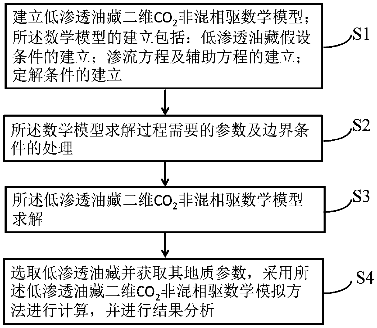
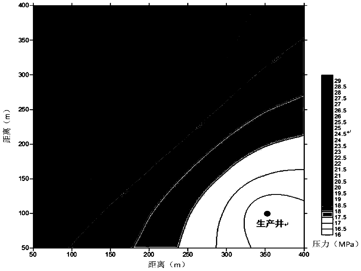
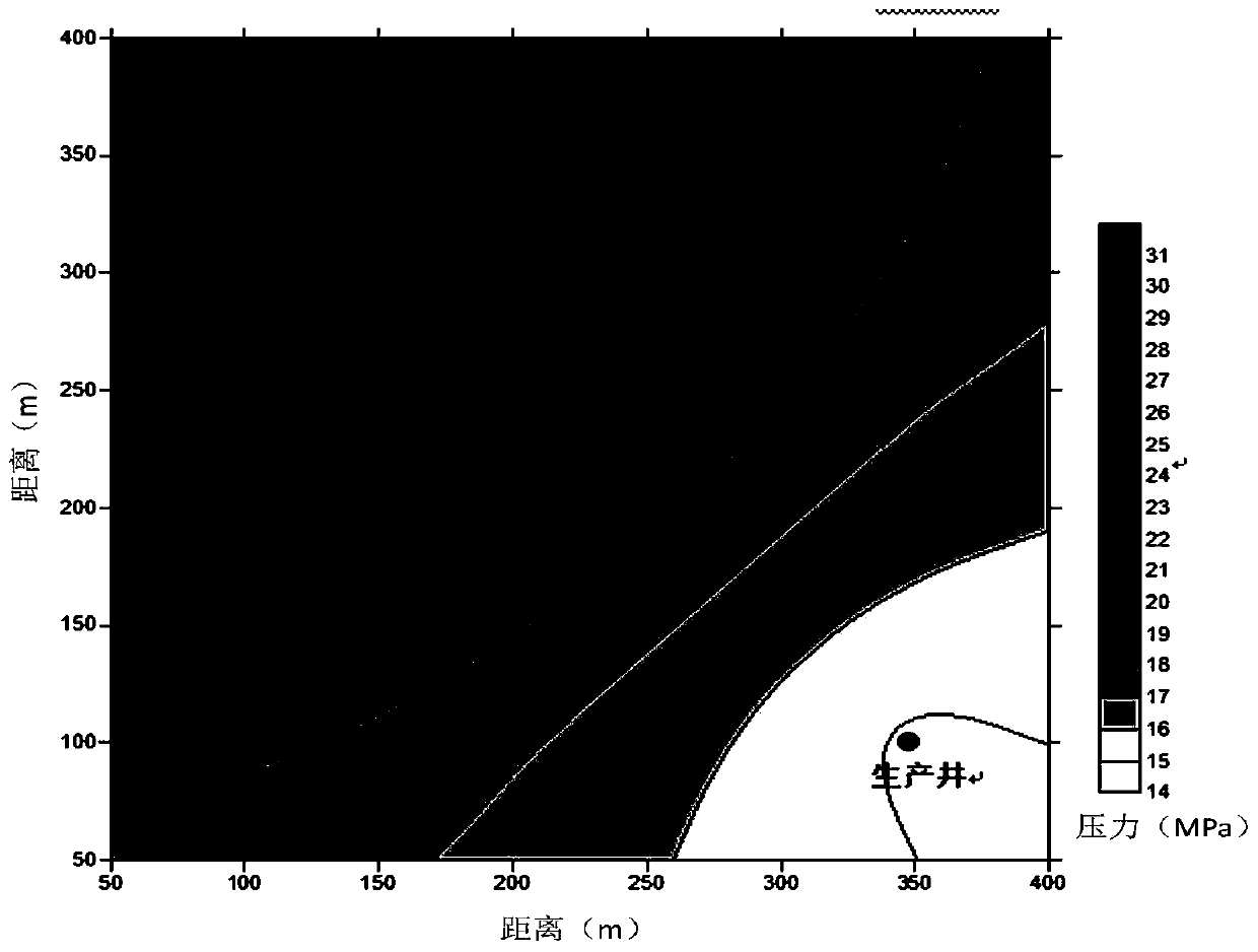
[0091] The technical scheme of the present invention will be described in detail and clearly below in conjunction with the application of the present invention in actual oil reservoirs. In the actual application process, the present invention presses figure 1 A low-permeability reservoir two-dimensional CO 2 Flow chart of immiscible flooding mathematical simulation method. The specific operation is shown in the following examples.

[0092] Step S1: Establish low permeability reservoir CO 2 Mathematical model of immiscible flooding;

[0093] The establishment of the mathematical model includes: the establishment of hypothetical conditions for low-permeability reservoirs; the establishment of seepage equations and auxiliary equations; the establishment of definite solution conditions; CO with fluid starting pressure gradient change 2 Mathematical model of immiscible flooding seepage;

[0094] Hypothetical conditions for low-permeability reservoirs include: (1) The fluid in...


PUM


Abstract

The invention provides a low-permeability oil reservoir two-dimensional CO2 immiscible displacement mathematical simulation method. The low-permeability oil reservoir two-dimensional CO2 immiscible displacement mathematical simulation method comprises the steps that a low-permeability oil reservoir two-dimensional CO2 immiscible displacement mathematical model is established; parameters and boundary conditions required in the low-permeability oil reservoir two-dimensional CO2 immiscible displacement solving process are processed; the low-permeability oil reservoir two-dimensional CO2 immiscible displacement mathematical model is solved, and the mathematical model is solved through a numerical method, that is, solving is conducted through an implicit pressure explicit saturation method; and a low-permeability oil reservoir is selected, geological parameters of the low-permeability oil reservoir are obtained, calculating is conducted through the low-permeability oil reservoir two-dimensional CO2 immiscible displacement mathematical simulation method, and results are analyzed. According to the low-permeability oil reservoir two-dimensional CO2 immiscible displacement mathematical simulation method, the change of crude oil viscosity and the change of the fluid start pressure gradient are considered in the CO2 immiscible displacement process, the low-permeability oil reservoir CO2 immiscible displacement mathematical model is established, the model is more similar to the actual properties of the oil reservoir, the solving method and the result analysis method are given, the calculation results are more reliable, and the low-permeability oil reservoir two-dimensional CO2 immiscible displacement mathematical simulation method is used for guiding development of low-permeability oil reservoir CO2 immiscible displacement.

Description

technical field [0001] The present invention relates to the technical field of oil and gas exploitation, more specifically, to a two-dimensional CO 2 Mathematical simulation method of immiscible flooding. Background technique [0002] CO 2 Oil flooding technology is the CO 2 A technology that is injected into an oil reservoir to enhance oil recovery from an oilfield. CO 2 The oil displacement mechanism mainly includes: (1) CO 2 It has good miscibility with crude oil and can significantly reduce the viscosity of crude oil; (2) CO 2 Soluble in crude oil and water, make it carbonated, improve the mobility ratio of crude oil and water; (3) CO 2 After being injected into the oil reservoir, the volume of the crude oil is greatly expanded, which can increase the elastic energy of the formation; (4) CO 2 Extraction and vaporization of light hydrocarbons in crude oil; (5) CO 2 After mixing with crude oil, it can not only extract and vaporize light hydrocarbons in crude oil, b...

Claims


Application Information

Patent Timeline
IPC IPC(8): E21B49/00E21B49/08E21B47/06E21B43/16G06F17/50
CPCE21B49/00E21B49/08E21B47/06E21B43/164G06F30/20Y02A10/40
Inventor 迟杰
Owner SHENGLI COLLEGE CHINA UNIV OF PETROLEUM
Learn More