Concrete pouring device and pouring method
A concrete and mounting frame technology, which is applied in construction, building structure, and building material processing, etc., can solve the problems of inaccurate control of vibration accuracy and speed, heavy manual labor, and low vibration efficiency.
- Summary
- Abstract
- Description
- Claims
- Application Information
AI Technical Summary
Problems solved by technology
Method used
Image
Examples
specific Embodiment approach 1
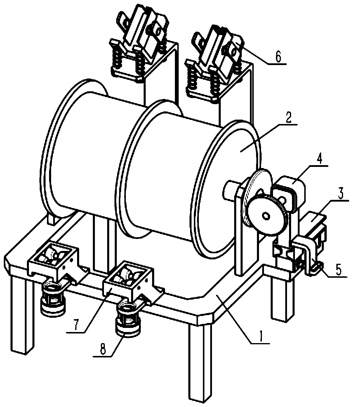
[0034] Such as Figure 1-10 As shown, a concrete pouring device includes a movable frame 1, a retractable roller 2, a variable speed carrier 3, a displacement power source 4, a positioner 5, a vibration-damping mounting frame 6, a first guide 7 and a second Two guides 8, the middle part of the movable frame 1 is rotatably connected to the retractable roller 2, the variable speed carrier 3 is fixedly connected to the movable frame 1, the displacement power source 4 is slidably connected to the variable speed carrier 3, and the variable speed carrier 3 is adjusted. The positioner 5 is fixedly connected to the displacement power source 4, the positioner 5 is engaged with the speed change carrier 3, the vibration-damping mounting frame 6 is fixedly connected to the front side of the movable frame 1, and the first guide 7 is connected to the movable The rear side of the frame 1 is fixedly connected, and the second guide 8 is fixedly connected to the lower end of the first guide 7 ....
specific Embodiment approach 2
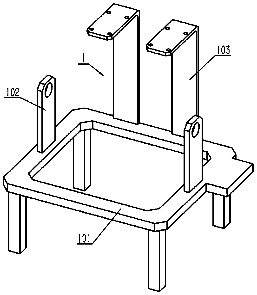
[0036] Such as Figure 1-10 As shown, the movable frame 1 includes a frame main body 101, a bearing with a seat 102 and a vibrator carrier 103, and the left and right sides of the middle part of the frame main body 101 are respectively fixedly connected with a bearing with a seat 102, and the vibrator is carried The frame 103 is fixedly connected to the front side of the frame main body 101 . Bearing with seat 102 is used for installing retractable roller 2, and vibrator carrier frame 103 is used for installing damping installation frame 6, refer to figure 1 , according to needs, the present invention can be set to different specifications, that is, to increase the number of vibration machine carriers 103, and correspondingly increase the number of first guides 7 and second guides 8, and the lower end of the frame body 101 can pass through Install on wheels or set up on mobile equipment to move.
specific Embodiment approach 3
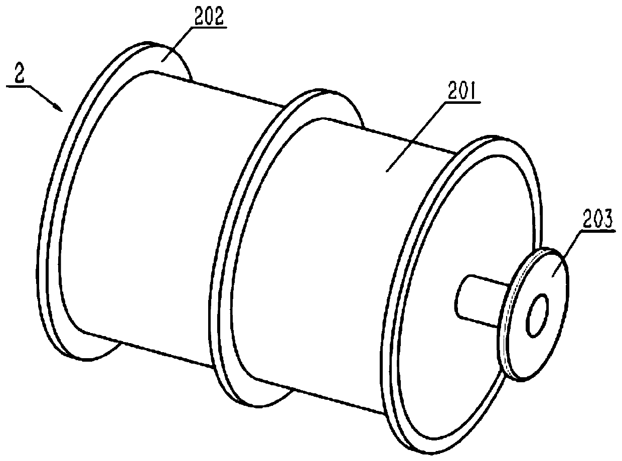
[0038] Such as Figure 1-10 As shown, the retractable roller 2 includes a retractable roller body 201, a partition ring 202 and a first friction disc 203, at least two partition rings 202 are fixedly connected to the retractable roller body 201, and the first friction disc 203 is fixedly connected On the main shaft at the right end of the retractable roller body 201 ; When the vibrator of the plug-in vibrator is wound up on the roll body 201, the position is restricted by two spacer rings 202, refer to image 3 At this time, there are three separating rings 202, and the vibrating rods of two plug-in vibrators can be rolled up on the retractable roller body 201, so that multiple vibrating rods can be inserted into the concrete at the same time as required.
PUM
 Abstract
Description
Claims
Application Information
 - R&D
- Intellectual Property
- Life Sciences
- Materials
- Tech Scout
- Unparalleled Data Quality
- Higher Quality Content
- 60% Fewer Hallucinations
Browse by: Latest US Patents, China's latest patents, Technical Efficacy Thesaurus, Application Domain, Technology Topic, Popular Technical Reports.
© 2025 PatSnap. All rights reserved.Legal|Privacy policy|Modern Slavery Act Transparency Statement|Sitemap|About US| Contact US: help@patsnap.com


