
Fabricated shear wall-in-column vertical main reinforcement installation structure and method

A technology for installing structures and shear walls, applied in the directions of structural elements, building components, building structures, etc., can solve problems such as troublesome disassembly and inconvenient installation, and achieve the effect of convenient torsion, increased friction, and increased fusion.

Active Publication Date: 2019-09-20
CHINA METALLURGICAL CONSTR ENG GRP
View PDF6 Cites 5 Cited by
  • Summary
  • Abstract
  • Description
  • Claims
  • Application Information

AI Technical Summary

Problems solved by technology

In the above-mentioned shear wall, the upper vertical steel bar and the lower vertical steel bar are mainly connected together by screw connection, but it is easy to confuse the connecting steel bar, the upper sleeve and the lower sleeve during the assembly process, and the installation is inconvenient. At the same time, it is more troublesome to disassemble after installation error

Method used


Image

  • Fabricated shear wall-in-column vertical main reinforcement installation structure and method
  • Fabricated shear wall-in-column vertical main reinforcement installation structure and method
  • Fabricated shear wall-in-column vertical main reinforcement installation structure and method

Examples


Embodiment

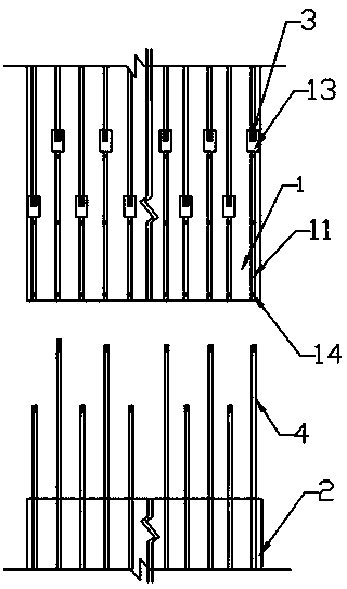
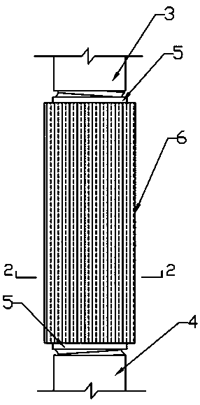
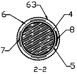
[0033] Such as Figure 1-Figure 6 As shown, the prefabricated shear wall-column vertical main reinforcement installation structure provided in this embodiment includes an upper wall column member 1 with a plurality of upper vertical reinforcement bars 3 inside and a lower wall column member 1 with a plurality of lower vertical reinforcement bars 4 inside. The wall column member 2, the lower vertical steel bar 4 of the lower wall column member 2 corresponds to the upper vertical steel bar 3 of the upper wall column member 1 one by one, and the upper end of the lower vertical steel bar 4 extends out of the lower wall column member 2 Outside the connecting end; inside the upper wall column member 1, there are a plurality of reserved blind holes 11 for placing the lower end of the upper vertical steel bar 3 inside and extending to the end of the connecting end of the upper wall column member 1; inside the lower wall column member 2 The protruding length of the protruding end of ea...


PUM


Abstract

The invention discloses a fabricated shear wall-in-column vertical main reinforcement installation structure and method. The fabricated shear wall-in-column vertical main reinforcement installation structure comprises an upper wall column member internally provided with a plurality of upper vertical reinforcement and a lower wall column member internally provided with a plurality of lower vertical reinforcement, wherein the upper wall column member is provided with a plurality of reserved operation holes; every two corresponding upper vertical reinforcement and lower vertical reinforcement are fixedly connected together through a connecting device, and the connecting devices each include an outer sleeve and two inner sleeves of which the inner walls are separately used for being in connection with the two corresponding vertical main reinforcement through threads; and the inner sleeves can be moved up and down in the length direction of the outer sleeves and can mesh with the outer sleeves after being rotated through tooth ripples, a plurality of arc-shaped through grooves are formed between the meshing outer sleeves and inner sleeves, and at least one arc-shaped through groove is internally provided with an arc-shaped clamping member tightly matched with the at least one arc-shaped through groove. According to the fabricated shear wall-in-column vertical main reinforcement installation structure and method, firm connection and convenient assembly operation are achieved.

Description

technical field [0001] The invention relates to a prefabricated building, in particular to a prefabricated shear wall-column vertical main reinforcement installation structure and an installation method thereof. Background technique [0002] The prefabricated shear wall is generally composed of an upper wall column member and a lower wall column member, and the upper and lower wall column members are connected by vertical steel bars arranged in the upper wall column member and the lower wall column member. During production, a plurality of reserved holes are provided in the upper wall column member, and the vertical steel bars in the lower wall column member are inserted into the corresponding reserved holes, and are sealed by grouting after welding or socket fitting. The method of grouting after the sleeve connection has high requirements for the construction workers, and it is inconvenient to promote. The structural strength of the welded connection is guaranteed, but the...

Claims


Application Information

Patent Timeline
Patent Type & Authority Applications(China)
IPC IPC(8): E04C5/16
CPCE04C5/165
Inventor 李红军刘辉张勤
Owner CHINA METALLURGICAL CONSTR ENG GRP
Learn More