
Bendable/twistable rolling conveyor guide

a conveyor guide and twisting technology, applied in the direction of conveyor parts, rollers, roller-ways, etc., can solve problems such as product spillage or skewed orientation, package jamming and possible damage, line stoppage,

Inactive Publication Date: 2005-01-20
SOLUS INDAL INNOVATIONS
View PDF19 Cites 16 Cited by
  • Summary
  • Abstract
  • Description
  • Claims
  • Application Information

AI Technical Summary

Benefits of technology

[0015] The present bendable / twistable rolling conveyor guide has several features, no single one of which is solely responsible for its desirable attributes. Without limiting the scope of this conveyor guide as expressed by the claims that follow, its more prominent features will now be discussed briefly. After considering this discussion, and particularly after reading the section entitled “Detailed Description of the Preferred Embodiments,” one will understand how the features of this conveyor guide provide advantages, which include ease of assembly and ability to be bent and twisted by the purchaser.
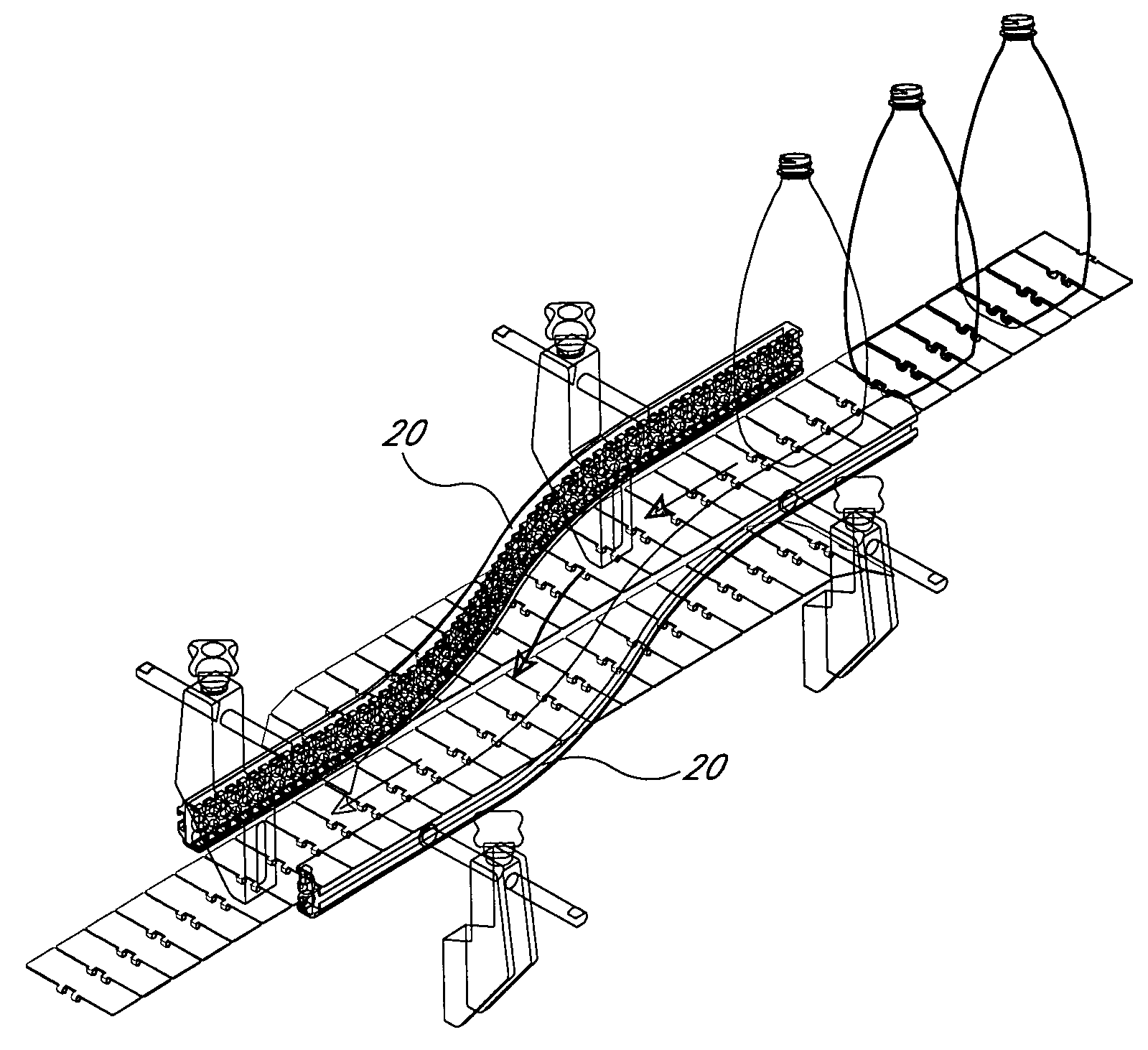
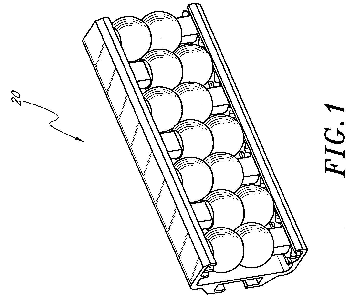
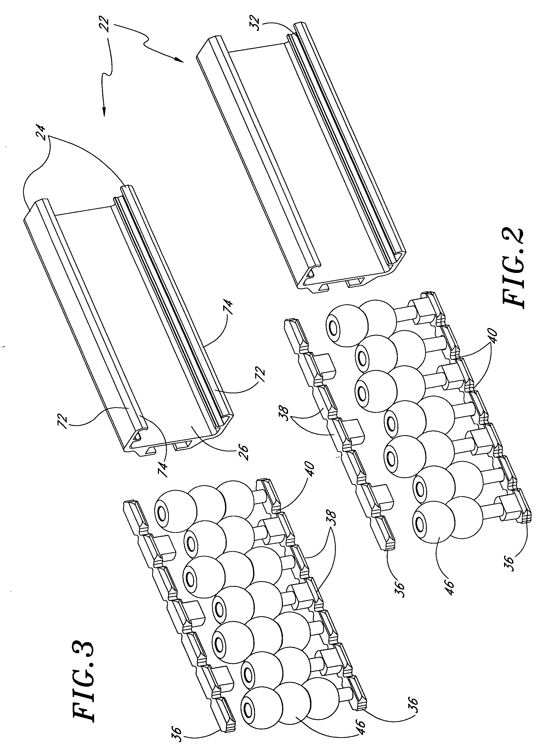
[0016] The present bendable / twistable rolling conveyor guide is easy to bend and twist, and is thus readily adaptable for use in any conveyor layout. In one embodiment, the bendable / twistable rolling conveyor guide includes any number of axles disposed between a pair of chain-like axle-positioning members. The axles serve as mounting points for rotatable elements such as rollers or beads. The axles and / or spacers may be molded integrally with the axle-positioning members. The axle-positioning members slidably engage two channels in a structural support member. The axle-positioning members are rigid but readily bendable and twistable. Evenly spaced notches cut in the edges of the axle-positioning member contribute to the ready bendability and twistability of the axle-positioning members. The shape of the notches ensures that the axle-positioning members do not interfere with the interior walls of the channels when the entire assembly is bent or twisted. In one embodiment, outer surfaces of the structural support member are shaped so as to mate with surfaces of a bending tool. Inter-engagement of the structural support member with the bending tool minimizes distortion of the structural support member during the bending operation. The structural support member is readily bent to theoretical radii as small as 5″. When constructed of a twistable material, the structural support member is readily twisted by hand to follow twisting sections of conveyor systems.

Problems solved by technology

Excess friction in any of these applications can cause line stoppage, package jamming and possible damage, product spillage or skewed orientation.
In powered conveyor applications especially, fixed guides generally provide too much friction to be useful, especially when a container or package must be guided around a turn or through a transfer from one conveyor to another.
However, applications for guides often require unique bead lengths.
Therefore, either each length must be amenable to being cut, bent and / or twisted by the purchaser to conform to each application, or the purchaser must special order the specific lengths and radii of guides needed, which is typically a more expensive option.
However, none of these guides are easily bent after they have been assembled.
Further, none of these guides is capable of being twisted.
Bending or twisting these guides often results in radical deformation of the supporting structure and even failure.
Therefore, none of these guides are well suited for use in curved or twisting sections of a conveying system unless they are custom manufactured to meet a particular customer's need.
These designs have some major drawbacks, however.
A plant layout requiring tighter radii would not be able to use these guides.
Second, because the device only bends between sections, and each section contains four axles, it does not provide an entirely smooth curve.
The transition points between sections have a tendency to catch passing articles on the conveyor, leading to jamming.
Third, neither of these guides is capable of being twisted.
The design of all of the above-mentioned guides also makes them more expensive to manufacture.
This is a very tedious process that is difficult to automate.

Method used


Image

  • Bendable/twistable rolling conveyor guide
  • Bendable/twistable rolling conveyor guide
  • Bendable/twistable rolling conveyor guide

Examples


Embodiment Construction

,” one will understand how the features of this conveyor guide provide advantages, which include ease of assembly and ability to be bent and twisted by the purchaser.

[0016] The present bendable / twistable rolling conveyor guide is easy to bend and twist, and is thus readily adaptable for use in any conveyor layout. In one embodiment, the bendable / twistable rolling conveyor guide includes any number of axles disposed between a pair of chain-like axle-positioning members. The axles serve as mounting points for rotatable elements such as rollers or beads. The axles and / or spacers may be molded integrally with the axle-positioning members. The axle-positioning members slidably engage two channels in a structural support member. The axle-positioning members are rigid but readily bendable and twistable. Evenly spaced notches cut in the edges of the axle-positioning member contribute to the ready bendability and twistability of the axle-positioning members. The shape of the notches ensures ...


PUM


Abstract

Readily bendable and twistable rolling conveyor guides are provided. The guides include axle-positioning members that slidably engage channels of a structural support member. A plurality of axles carrying rotatable elements and spacers are disposed between the axle-positioning members. Certain embodiments include notches in the axle-positioning members. Certain other embodiments include unique cross-sections at the exterior of the channels. Advantageously, the assembled guides may be bent without causing distortion of the channels or interference between the axle-positioning members and the channels. In certain other embodiments, the support structures of the guides are constructed of flexible materials. The guides are thus readily twistable about longitudinal axes thereof.

Description

RELATED APPLICATIONS [0001] This application is a continuation-in-part of copending application Ser. No. 10 / 789,629, filed on Feb. 27, 2004, which is a continuation-in-part of application Ser. No. 10 / 366,592, filed on Feb. 11, 2003, now abandoned, which is a continuation of application Ser. No. 09 / 706,460, filed on Nov. 3, 2000, now U.S. Pat. No. 6,516,933. The entire contents of these applications are hereby expressly incorporated by reference.BACKGROUND OF THE INVENTION [0002] 1. Field of the Invention [0003] The present invention relates to guides for installation along the sides of a container-transporting conveyor system. More specifically, the present bendable / twistable rolling conveyor guide is adapted for installation along straight, curved and / or twisting sections of a conveyor system. [0004] 2. Description of the Related Art [0005] Guides mounted on opposite sides of conveying systems are used in a variety of places in industrial installations. For example, they are used f...

Claims


Application Information

Patent Timeline
IPC IPC(8): B65G21/20
CPCB65G21/2054
Inventor LEDINGHAM, STUART J.
Owner SOLUS INDAL INNOVATIONS
Learn More