Decontamination electrolyte and decontamination method
An electrolyte and electrochemical technology, which is applied in the field of radioactive pollutant treatment, can solve problems such as difficult treatment and large output of decontamination waste liquid
- Summary
- Abstract
- Description
- Claims
- Application Information
AI Technical Summary
Problems solved by technology
Method used
Image
Examples
Embodiment approach
[0032] The decontamination method of one embodiment, comprises the following steps:
[0033] The workpiece to be decontaminated is subjected to electrochemical removal treatment with the above-mentioned decontamination electrolyte.
[0034] Specifically, the workpiece to be decontaminated is placed in the above-mentioned decontamination electrolyte for electrochemical decontamination treatment to obtain a decontaminated workpiece. Further, the workpiece to be decontaminated is placed as an anode in the decontamination electrolyte, and the power is turned on for electrolysis to obtain a decontaminated workpiece.
[0035] In one of the embodiments, the current density of the electrochemical decontamination treatment is 1000A / m 2 ~1200A / m 2 . Preferably, the current density of the electrochemical decontamination treatment is 1100A / m 2 ~1200A / m 2 . In one embodiment, the temperature of the electrochemical decontamination treatment is 30°C-50°C. Preferably, the temperature o...
specific Embodiment
[0041] The following will be described in detail in conjunction with specific embodiments. The following examples do not include other components except unavoidable impurities unless otherwise specified. The drugs and instruments used in the examples are all routine choices in the art unless otherwise specified. The experimental methods for which specific conditions are not indicated in the examples are implemented according to conventional conditions, such as the conditions described in literature, books or the method recommended by the manufacturer.
Embodiment
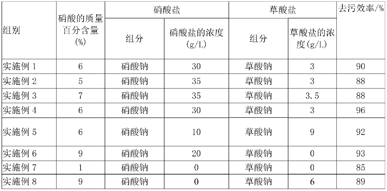
[0043] (1) Use water as a solvent to prepare the decontamination electrolytes of Examples 1 to 8, wherein the components of the decontamination electrolytes of each embodiment and the content of each component in the decontamination electrolyte are as shown in Table 1 .
[0044] (2) Take 24 workpieces to be decontaminated, weigh and record the mass of the sample (the size of the sample is: length*width*thickness=50mm*10mm*3mm), and then randomly divide them into 8 groups, each group corresponds to a In an embodiment, electrochemical decontamination treatment is performed. Specifically, the workpiece to be decontaminated is Z2CN18.10 austenitic stainless steel, the workpiece to be decontaminated is an anode, a titanium plate is selected as a cathode, and the current density is 1000A / m 2 , the temperature of the electrolyte is 40° C., and the time of the electrochemical decontamination treatment is 10 min. After the electrochemical decontamination treatment, the workpieces sub...
PUM
 Abstract
Description
Claims
Application Information
 - R&D
- Intellectual Property
- Life Sciences
- Materials
- Tech Scout
- Unparalleled Data Quality
- Higher Quality Content
- 60% Fewer Hallucinations
Browse by: Latest US Patents, China's latest patents, Technical Efficacy Thesaurus, Application Domain, Technology Topic, Popular Technical Reports.
© 2025 PatSnap. All rights reserved.Legal|Privacy policy|Modern Slavery Act Transparency Statement|Sitemap|About US| Contact US: help@patsnap.com

