Stamping machine

A stamping machine, a pair of technology, applied in the field of stamping machines, to achieve the effect of improving stamping efficiency, ensuring clarity, and reducing labor load

Active Publication Date: 2019-09-20
XUZHOU UNIV OF TECH
View PDF5 Cites 1 Cited by
  • Summary
  • Abstract
  • Description
  • Claims
  • Application Information

AI Technical Summary

Problems solved by technology

[0003] Aiming at the problems existing in the above-mentioned prior art, the present invention provides a stamping machine, which can replace the manual stamping operation by machinery, can ensure better clarity of the imprint, and can improve the efficiency of the stamping operation, and at the same time , it is not easy to leak the cover, and can reduce the labor load of the operator

Method used


Image

  • Stamping machine
  • Stamping machine
  • Stamping machine

Examples


Embodiment Construction

[0023] The present invention will be further described below.

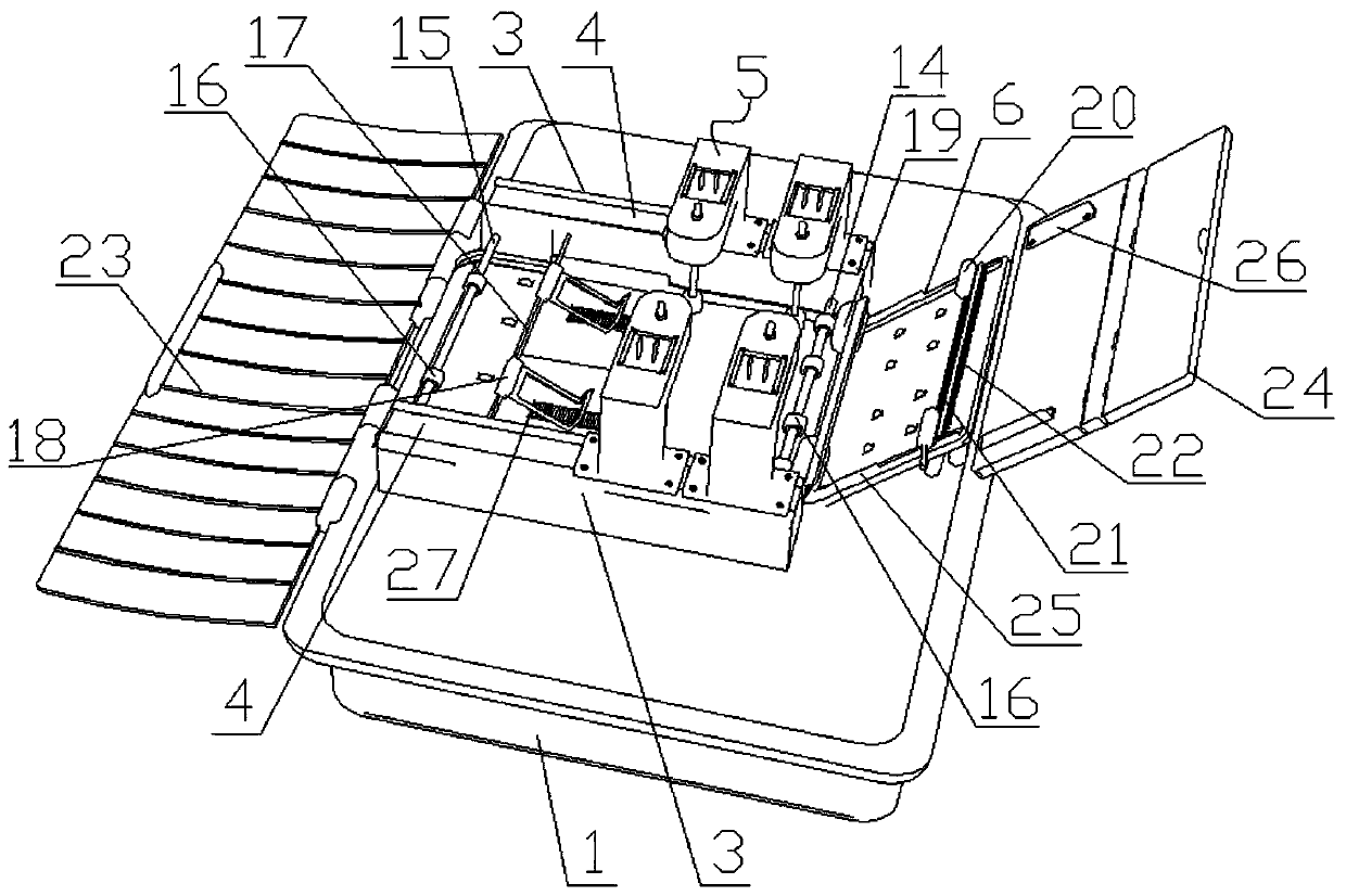
[0024] Such as Figure 1 to Figure 3 As shown, a stamping machine includes a base 1 and a machine case 2 fixedly connected to the top of the base 1, the machine case 2 is composed of a bottom plate and a cover body; A paper outlet, the bottom of the other end is provided with a paper outlet; a controller is also included; a pair of support rails 3 are arranged parallel to the top of the bottom plate of the machine housing 2, and a paper passage is formed at the bottom between the pair of support rails 3; A pair of slide grooves 4 are arranged in parallel on the upper end faces of a pair of supporting rails 3; two stamping mechanisms 5 are arranged on each supporting rail 3;

[0025] The bottom plate of the machine casing 2 is provided with an inclined support plate 6 on one side of the paper inlet, the upper end of the inclined support plate 6 communicates with the paper inlet, and its lower end extends to the pa...


PUM


Abstract

A stamping machine is characterized in that a pair of supporting rails is arranged at the upper part of a bottom plate of a housing, wherein chutes are formed in the upper end surfaces of the supporting rails, and two stamping mechanisms are arranged in the chutes; an inclined supporting plate is arranged at one side, at a paper feeding port, of the bottom plate of the machine housing; each stamping mechanism comprises a supporting frame, a vertical lifting column, a supporting arm, a connecting rod and an electric pushing rod; a first rotating shaft, a second rotating shaft and a third rotating shaft are correspondingly arranged between the bottom parts of the supporting rails; two ends of the first rotating shaft, the second rotating shaft and the third rotating shaft are rotatably connected between the supporting rails; the first rotating shaft and the second rotating shaft are fixedly sleeved with a plurality of paper guide rollers A; two paper pressing racks fixedly sleeve the third rotating shaft; two fourth rotating shafts are connected to the paper feeding ends between the bottom parts of the supporting rails; the fourth rotating shafts fixedly sleeve paper guide rollers B; a pair of paper guide rollers C is arranged at the upper end of the inclined supporting plate; and a pair of paper limiting plates A is oppositely mounted at two sides of the inclined supporting plate. The stamping machine is high in working efficiency; and moreover, the workload of operators can be decreased.

Description

technical field [0001] The invention relates to a stamping machine. Background technique [0002] In some application occasions, it is necessary to perform stamping operations on documents in large quantities. In the prior art, stamping operations are mostly done manually. There will be a leakage of the cover, and the labor load of the operator is relatively large. Contents of the invention [0003] Aiming at the problems existing in the above-mentioned prior art, the present invention provides a stamping machine, which can replace the manual stamping operation by machinery, can ensure better clarity of the imprint, and can improve the efficiency of the stamping operation, and at the same time , It is not easy to leak the cover, and can reduce the labor load of the operator. [0004] In order to achieve the above object, the present invention provides a stamping machine, comprising a base and a casing fixedly connected to the upper part of the base, the casing is compose...

Claims


Application Information

Patent Timeline
Patent Type & Authority Applications(China)
IPC IPC(8): B41K3/04
CPCB41K3/04
Inventor 刘丽丽陶开昕杨丽娟
Owner XUZHOU UNIV OF TECH
Why Eureka
Try Eureka