
Automatic cleaning system of indoor air conditioner

An automatic cleaning and air-conditioning technology, which is applied in the field of air-conditioning, can solve the problems of too many filters, the filter blocks the air flow, and affects the cooling and heating effect of the air-conditioning, so as to achieve the effect of clean ventilation of the air-conditioning and ensure the ventilation of the air-conditioning

Active Publication Date: 2019-09-20
湖南省宝满科技开发有限公司
View PDF10 Cites 3 Cited by
  • Summary
  • Abstract
  • Description
  • Claims
  • Application Information

AI Technical Summary

Problems solved by technology

[0003] After the air conditioner has been used for a long time, the filter screen of the air conditioner will have more impurities. If it is not cleaned or dredged, the filter screen will be blocked and the air flow will be blocked, which will affect the air flow inside the air conditioner. Cooling and heating effect of air conditioner
Moreover, the air passing through the dirty air-conditioning filter increases inhalable particulate matter that is harmful to the human body. The air-conditioning blows this air, which increases the concentration of PM2.5 in the room and affects people's health. At present, the cleaning of the air-conditioning filter is mainly It is a regular cleaning based on experience. In this way, the speed at which the filter accumulates impurities changes with different environments. In the time of experience, due to environmental effects, the filter accumulates impurities that exceed expectations, causing the filter to lose its filtering effect. It also leads to an increase in the PM2.5 of the filtered air, which has a health impact on the users of the air conditioner

Method used


Image

  • Automatic cleaning system of indoor air conditioner
  • Automatic cleaning system of indoor air conditioner
  • Automatic cleaning system of indoor air conditioner

Examples


Embodiment Construction

[0029] The present invention will be further described below in conjunction with the accompanying drawings and embodiments.

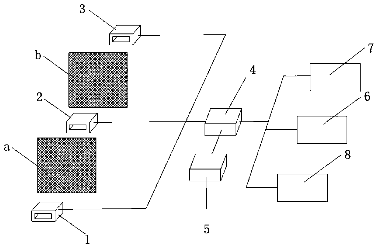
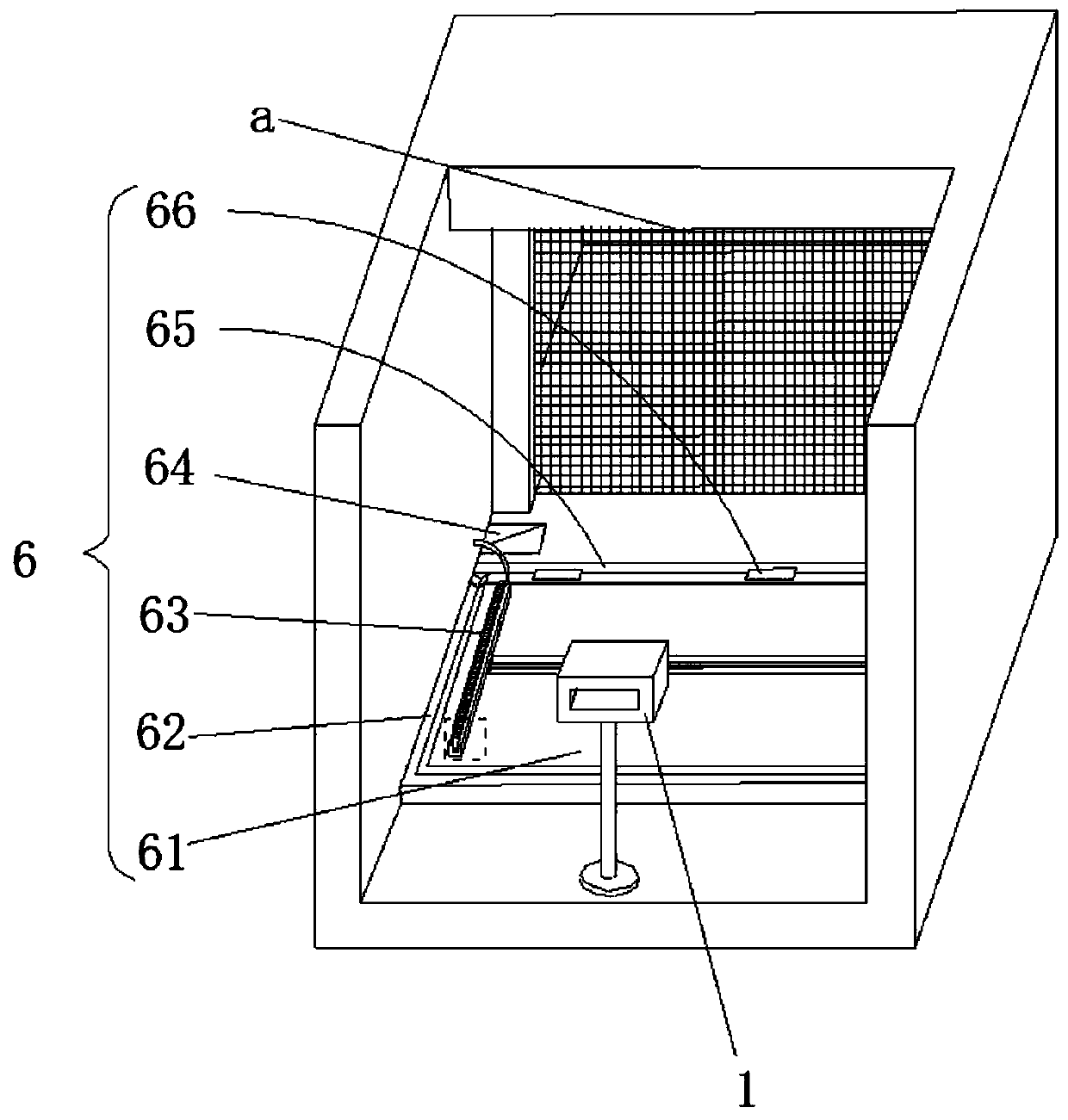
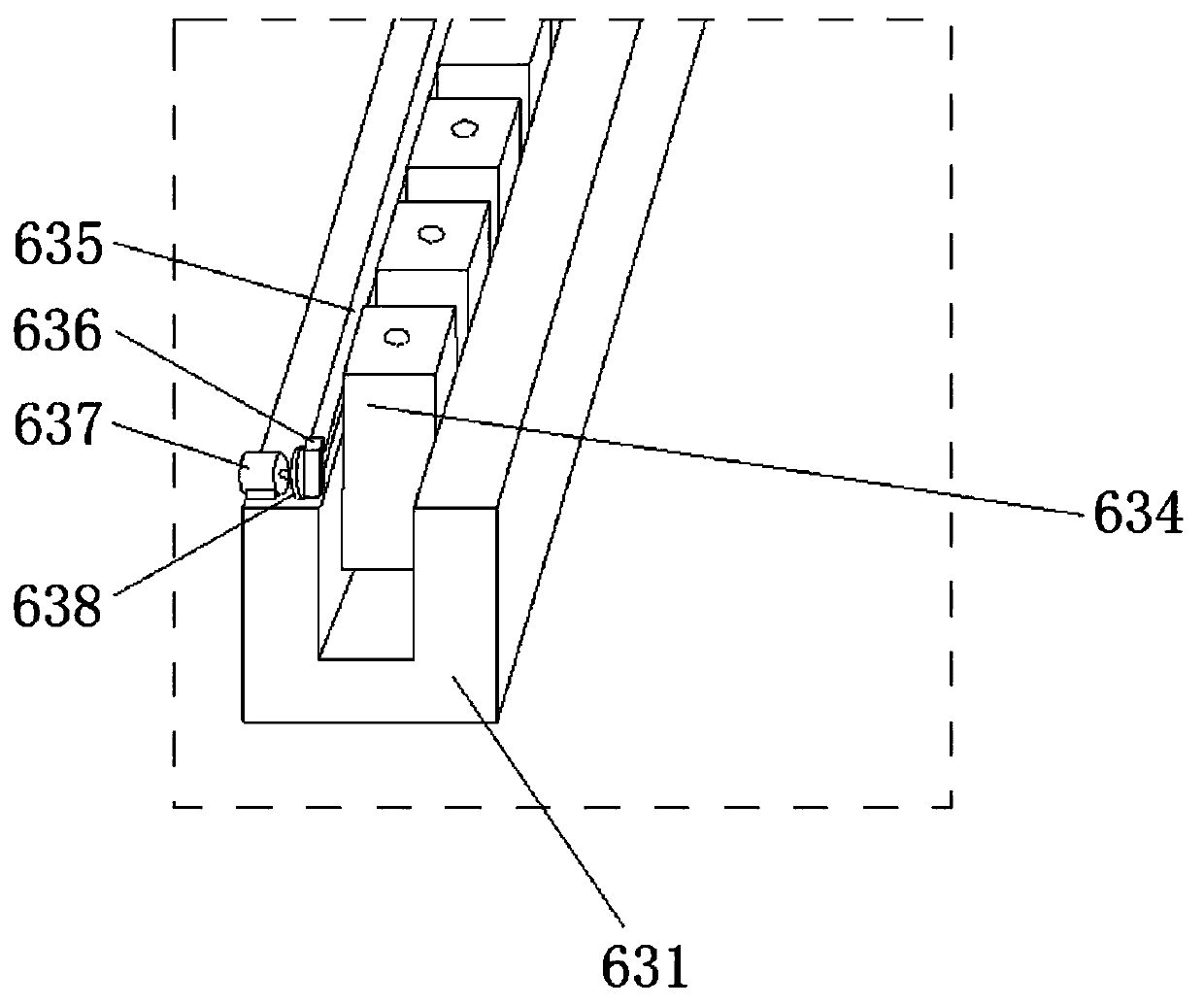
[0030] Please refer to figure 1 , figure 2 , image 3 , Figure 4 , Figure 5 , Figure 6 , Figure 7 , Figure 8 as well as Figure 9 ,in figure 1 The structural block diagram of the automatic cleaning system of the indoor air conditioner provided by the present invention; figure 2 for figure 1 The structural schematic diagram of the first cleaning mechanism shown; image 3 for figure 2 An enlarged schematic view of the structure at the indicated dashed line; Figure 4 for figure 2 Schematic diagram of the structure of the rotating plate shown; Figure 5 for figure 2 The schematic cross-sectional view of the structure of the multi-port nozzle shown; Figure 6 for figure 1 The structural schematic diagram of the second cleaning mechanism shown; Figure 7 for Figure 6 A schematic sectional view of the structure of the second cleani...


PUM


Abstract

The invention provides an automatic cleaning system of an indoor air conditioner. The automatic cleaning system comprises a first PM2.5 (particulate matter 2.5) detection mechanism, a second PM2.5 detection mechanism, a third PM2.5 detection mechanism, a storage mechanism, an air conditioner display, a first cleaning mechanism and a second cleaning mechanism, wherein the components all electrically communicate with a controller; the first PM2.5 detection mechanism is arranged outside an air inlet filtering net a of an air conditioner air introduction channel; the second PM2.5 detection mechanism is arranged between the air inlet filtering net a and an air outlet filtering net b; the third PM2.5 detection mechanism is arranged outside the air outlet filtering net b; the first cleaning mechanism is used for cleaning the air inlet filtering net a; and the second cleaning mechanism is used for cleaning the air outlet filtering net b. By adopting the automatic cleaning system of the indoor air conditioner, the situation that normal operation of the air conditioner is affected by accumulated dust on the air inlet filtering a and the air outlet filtering net b can be fed back to a user in time, and in addition, the air inlet filtering net a and the air outlet filtering net b can be automatically cleaned.

Description

technical field [0001] The invention relates to the field of air conditioners, in particular to an automatic cleaning system for indoor air conditioners. Background technique [0002] Air conditioners have become one of the most commonly used electrical equipment in daily life. Air conditioners control indoor temperature, humidity and other parameters by adjusting the temperature and flow of air. During the operation of the air conditioner, in order to be able to output clean air, the air needs to be filtered. At present, the most widely used filtering method is to set a filter screen at the air inlet and outlet to filter the dust and impurities in the air intake and outlet air. The filter screen can filter the output air conveniently and quickly, but with the use of time increase, the filter needs to be cleaned or replaced to ensure the normal filtering effect of the purification module. [0003] After the air conditioner has been used for a long time, the filter screen o...

Claims


Application Information

Patent Timeline
IPC IPC(8): B01D46/12B01D46/00G01N15/06
CPCB01D46/12G01N15/06B01D46/681
Inventor 曹俊
Owner 湖南省宝满科技开发有限公司
Learn More