
Non-excavation drilling machine dragging tube and maintenance construction method thereof

A trenchless pipe-drawing technology, applied to pipes, rigid pipes, flange connections, etc., can solve the problems of inconvenient maintenance and use, inconvenient excavation of the soil layer, and difficulty in judging the damage position of the drag pipe, etc., to achieve the best results Better and convenient maintenance and replacement work effect

Active Publication Date: 2019-09-17
上海信立生态环境工程有限公司
View PDF7 Cites 2 Cited by
  • Summary
  • Abstract
  • Description
  • Claims
  • Application Information

AI Technical Summary

Problems solved by technology

Since the drag tube is placed in the soil layer, and the soil layer is inconvenient to dig, it is difficult for the staff to judge the specific damage location of the drag tube, resulting in inconvenient maintenance and use. Therefore, a new solution needs to be proposed to solve this problem

Method used


Image

  • Non-excavation drilling machine dragging tube and maintenance construction method thereof
  • Non-excavation drilling machine dragging tube and maintenance construction method thereof
  • Non-excavation drilling machine dragging tube and maintenance construction method thereof

Examples


Embodiment 1

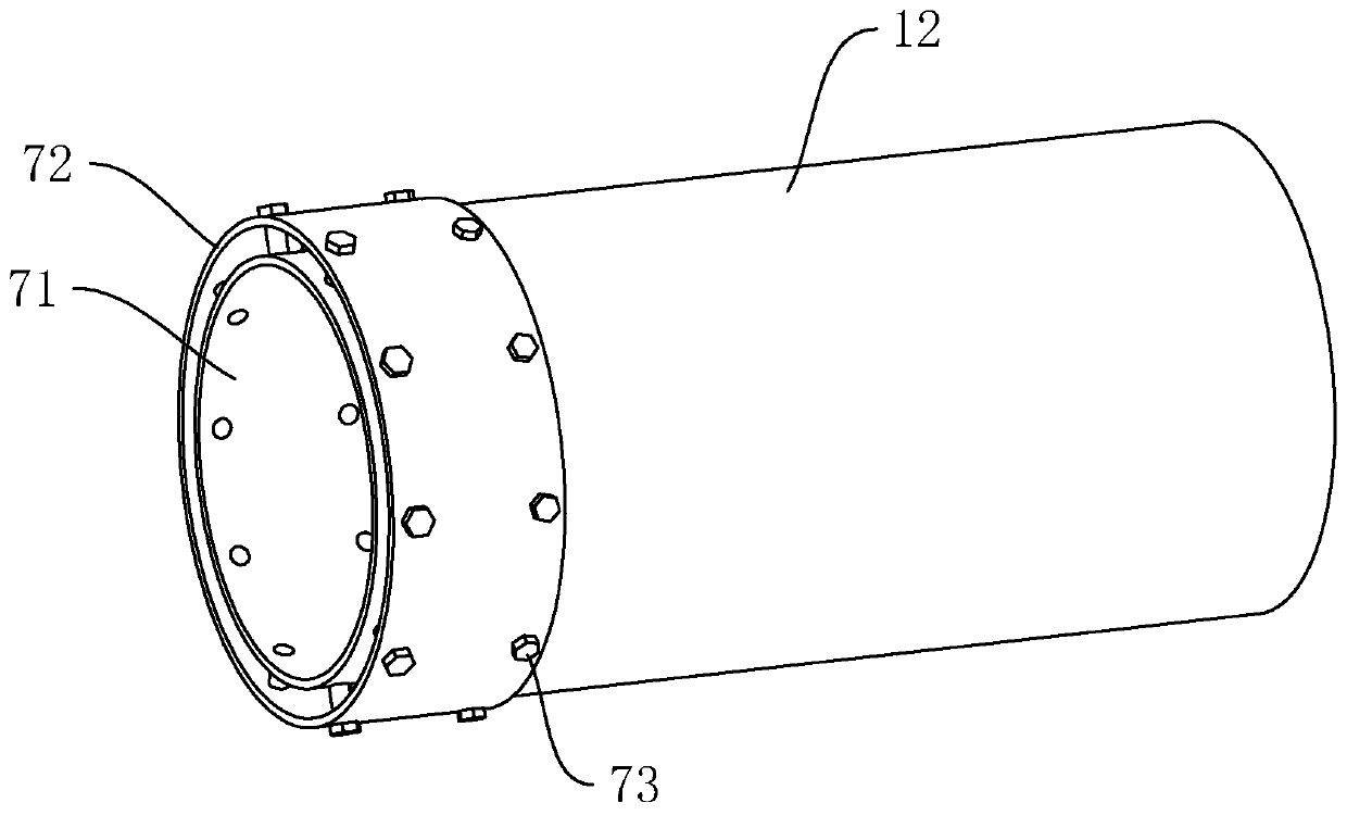
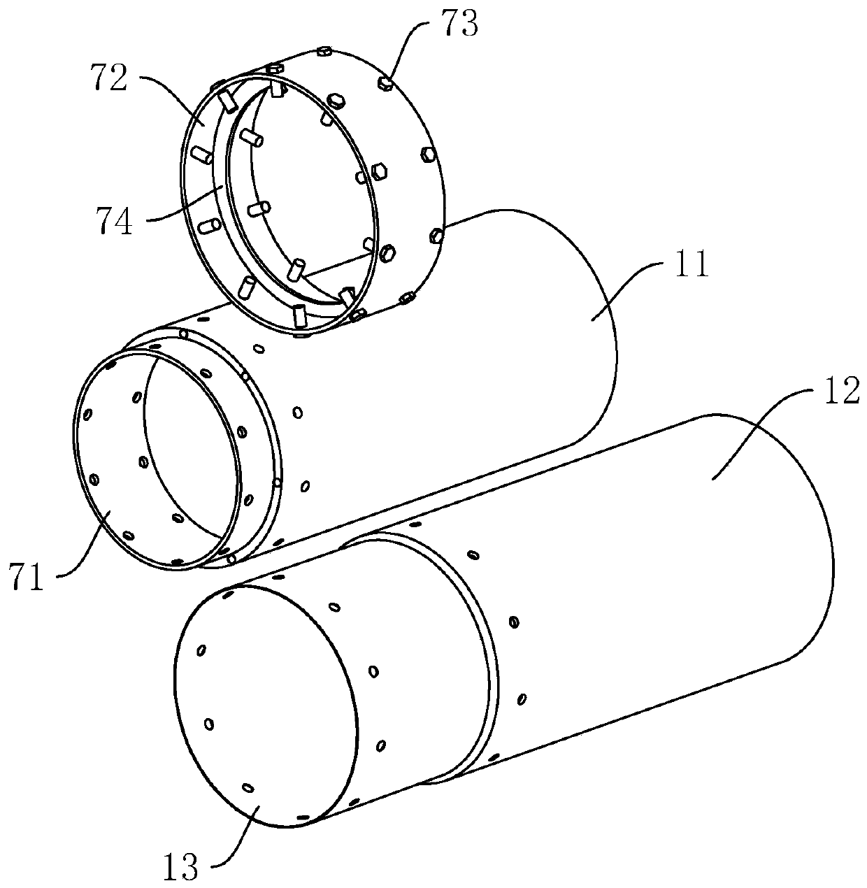
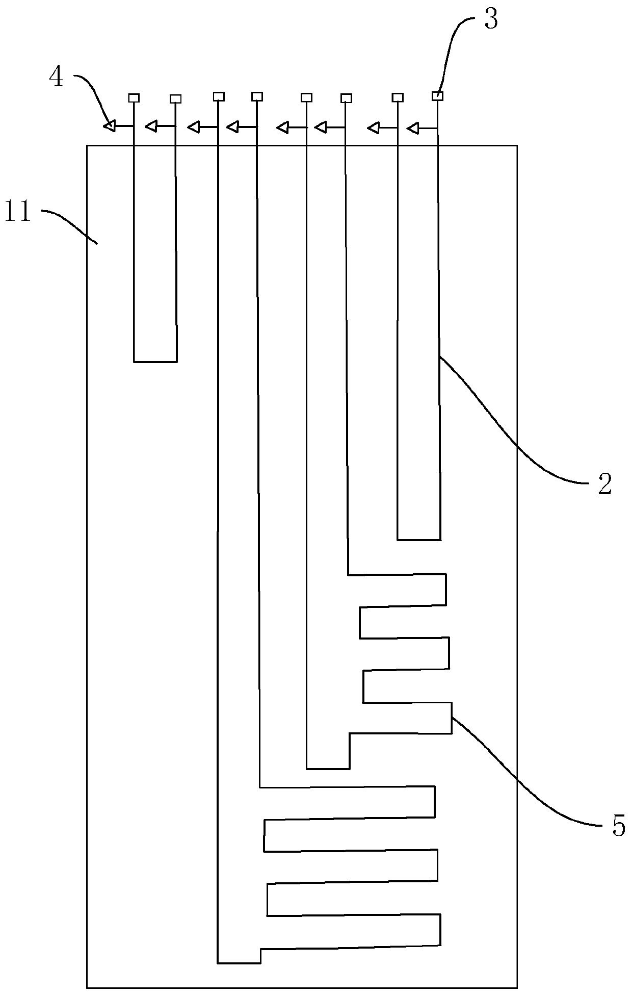
[0037] Trenchless drilling rig pull pipe, see figure 1 with figure 2 , including an inner tube 11 and an outer tube 12 coated and fixed outside the inner tube 11, a plurality of conductive wires 2 are arranged between the inner tube 11 and the outer tube 12, and the plurality of conductive wires 2 are distributed around the inner tube 11 in a circumferential direction . The reason why the conductive thread 2 is arranged between the inner tube 11 and the outer tube 12 is that an electric current needs to be passed on the conductive thread 2, and the damaged position of the drag tube can be judged by means of the electric current.

[0038] The inner tube 11 is made of insulating rubber, and a plurality of reinforcing wires 111 (marked on Figure 5 ); a plurality of reinforcing wires 111 are evenly distributed around the inner tube 11 in the circumferential direction, and metal wires can be selected.

[0039] The outer tube 12 is a wear-resistant tube, which can be made of FE...

Embodiment 2

[0057] The maintenance and construction method applied to the drag pipe of the non-excavation drilling rig, including:

[0058] Step 1. Obtain the damage information of the underground pipeline, delineate the area where the expected damage point is located, install protective fences and safety signs in the construction area, and move construction machinery, tools, and materials into the construction area;

[0059] Step 2. Determine the positions of the front and rear ends of the damaged pipeline according to the original pipeline layout drawings, and excavate them as pits No. 1 and No. 2;

[0060] Step 3: Workers enter the No. 1 pit or No. 2 pit, turn and disassemble the fixing bolt 73, so that the inner tube 11 and the outer tube 12 of another drag tube are no longer connected by the inner end of the drag tube end that needs to be repaired. The pipe 71 and the connecting pipe 72 at the outer end are clamped and fixed, and then the pulling pipe to be repaired and another pulli...


PUM


Abstract

The invention discloses a non-excavation drilling machine dragging tube and a maintenance construction method thereof, relates to the pipeline engineering field, and aims at solving the problems that damage positions of an existing dragging tube are inconvenient to confirm, and therefore the existing dragging tube is inconvenient to maintain or replace, and use effects are influenced. The main point of the technical scheme is that the non-excavation drilling machine dragging tube comprises an inner tube and an outer tube fixed on the exterior of the inner tube in wrapping mode, wherein a plurality of electric conduction wires used for determining the damage positions of a pipeline are arranged between the inner tube and the outer tube, the plurality of the electric conduction wires are distributed around the circumferential direction of the wall face of the inner tube, and joints are respectively fixed on end portions of the electric conduction wires. The non-excavation drilling machine dragging tube and the maintenance construction method thereof can relatively facilitate damage position positioning for workers so as to facilitate replacement, and thereby are good in use effect.

Description

technical field [0001] The invention relates to the field of pipeline engineering, more specifically, it relates to a non-excavation drilling rig pulling a pipe and a maintenance construction method thereof. Background technique [0002] Trenchless refers to the use of various geotechnical drilling equipment and technical means to excavate a very small part of the surface (generally refers to small-area excavation at the entrance and exit) through guided and directional drilling. And the new construction technology for repairing various underground pipelines will not hinder traffic, will not damage green land and vegetation, will not affect the normal life and work order of shops, hospitals, schools and residents, and solve the traditional excavation construction. Disturbance, damage and adverse effects on traffic, environment, surrounding building foundations, thus having high socio-economic effects. [0003] When applying trenchless technology, the pipeline laid by it can...

Claims


Application Information

Patent Timeline
Patent Type & Authority Applications(China)
IPC IPC(8): F16L9/14F16L23/04F17D5/00
CPCF16L9/14F16L23/003F16L23/04F17D5/00
Inventor 黄志平
Owner 上海信立生态环境工程有限公司
Learn More