
Pneumatic tire

A technology of pneumatic tires and treads, which is applied to tire parts, tire treads/tread patterns, transportation and packaging, etc., which can solve problems such as inability to meet the driving needs of all-season tires, and ensure wet handling and driving stability , snow driving stability and handling improvement, performance optimization effect

Active Publication Date: 2019-09-17
CHENG SHIN RUBBER CHINA
View PDF27 Cites 7 Cited by
  • Summary
  • Abstract
  • Description
  • Claims
  • Application Information

AI Technical Summary

Problems solved by technology

[0003] In recent years, with the warming of the global temperature, the ice and snow covered roads in some areas have decreased in winter. Therefore, the demand for driving performance on dry and wet roads under non-snow road conditions in winter driving has continued to increase. However, due to the existing all-season tires focusing on Snow driving performance, so it cannot meet the actual road conditions of all-season tires at this stage.

Method used


Image

  • Pneumatic tire
  • Pneumatic tire
  • Pneumatic tire

Examples


Embodiment Construction

[0029] The purpose of this specific embodiment is to provide a pneumatic tire, which has excellent driving performance in dry, wet and snowy road conditions, and can fully meet the driving requirements of the vehicle in four seasons.

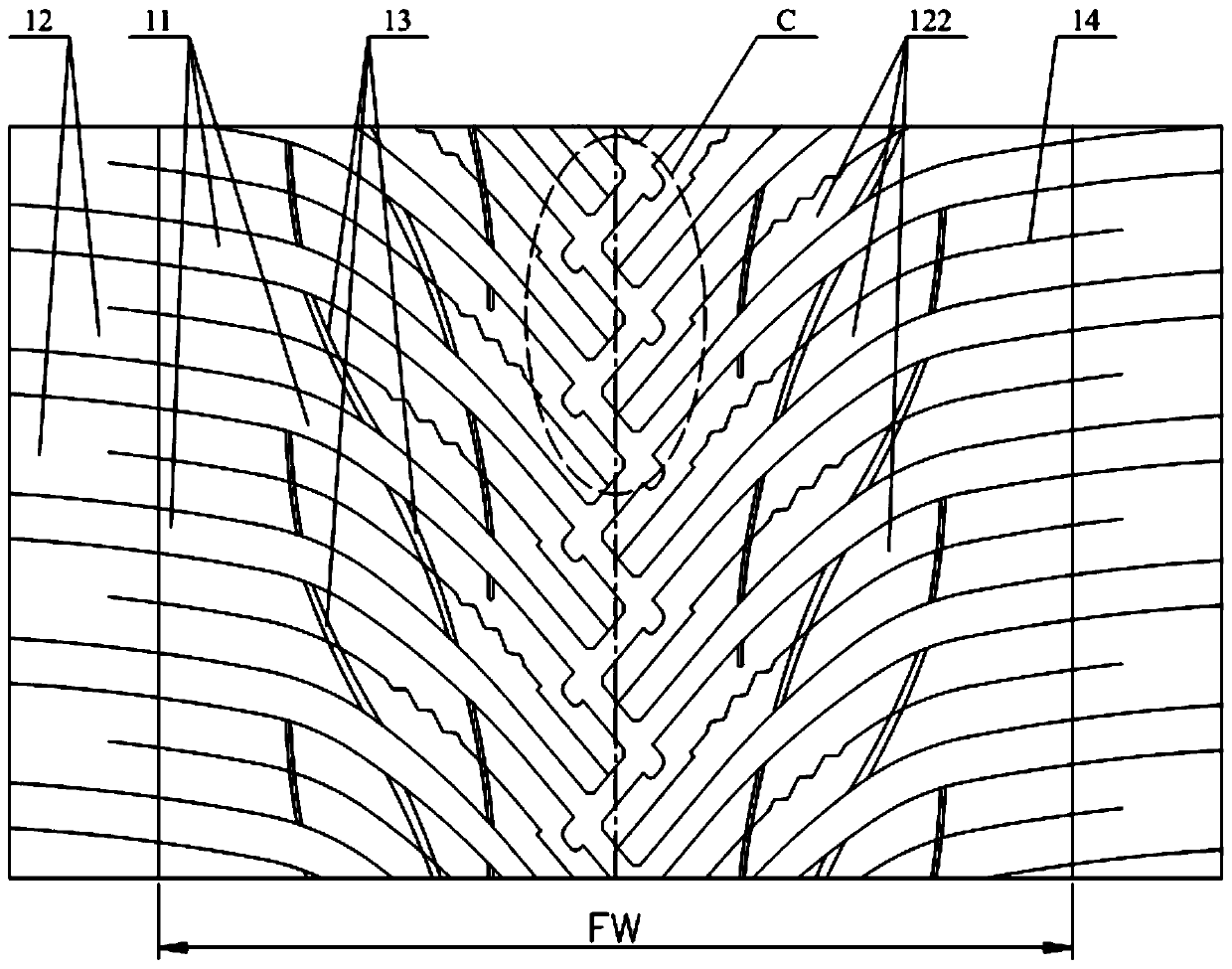
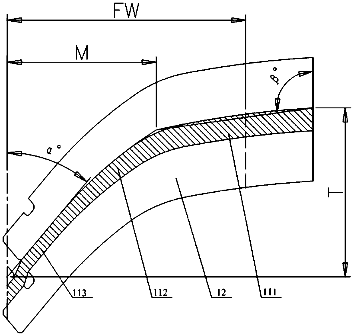
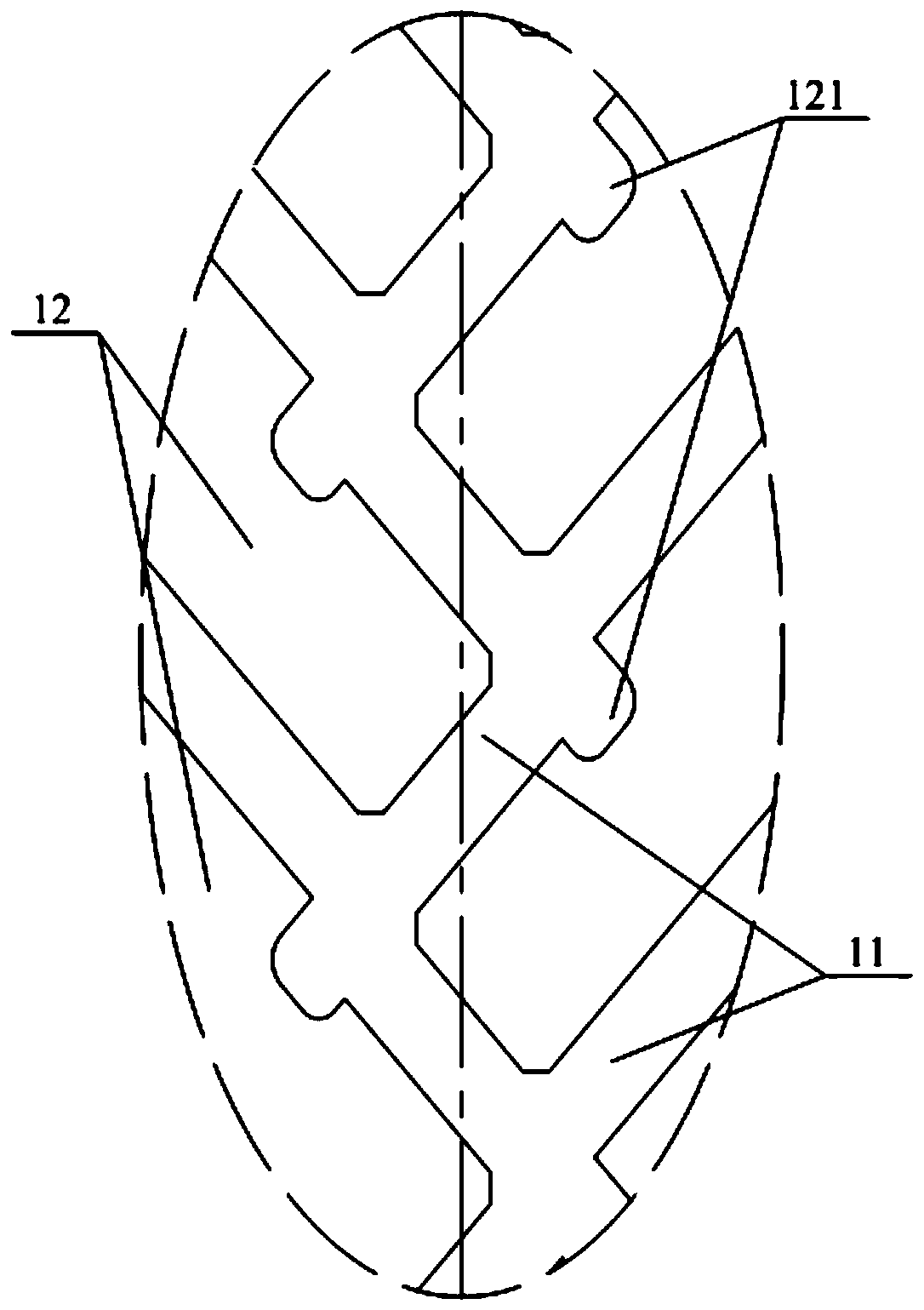
[0030] Please refer to Figure 1-Figure 8 , figure 1 It is a structural schematic diagram of the main tread part of the pneumatic tire provided in a specific embodiment of the present invention; figure 2 for figure 1 Schematic diagram of the structure of the middle main groove; image 3 for figure 1 The enlarged view of the local structure of part C in the middle; Figure 4 for figure 1 Schematic diagram of the position distribution of the middle longitudinal thin sipe; Figure 5 for Figure 4 Size comparison diagram of each part of the middle longitudinal thin sipe; Figure 6 for figure 1 Schematic diagram of the structure of the middle horizontal thin sipe; Figure 7 It is an axial schematic diagram of a partial structure of a pneum...


PUM


Abstract

The invention discloses a pneumatic tire. A plurality of main ditches extending along the two side edges of a main tread to the middle part of the main tread are formed in the main tread; tread ribs in contact with the ground are formed between the two adjacent main ditches; with the circumferential central line of the main tread as reference, the main ditches positioned on the same side of the circumferential central line are uniformly distributed in parallel in the circumferential direction of the main tread; and the main ditches positioned on the two sides of the circumferential central line are arranged in a staggered and crossed manner; the internal end parts of the two main ditches positioned on the opposite sides of the circumferential central line and adjacent to each other in the circumferential direction of the main tread are intersected at the middle part of the main tread; by using a straight line, which is made to pass through any point at the external end part of the central line of the main ditch and extends in the axial direction of the tire, as an axial reference line, the distances between the central lines of the main ditches and the axial reference line are gradually increased from the external ends of the main ditches to the internal ends of the main ditches, and the widths of the main ditches are gradually reduced from the external ends of the main ditches to the internal ends of the main ditches. The running performance of the pneumatic tire under road conditions of dry land, wet land and snowfield is more excellent, and the pneumatic tire can sufficiently satisfy running demands of a vehicle under four-season road conditions.

Description

technical field [0001] The present invention relates to the technical field of pneumatic tires, more specifically, to a pneumatic tire. Background technique [0002] In some European countries in the frigid or sub-frigid zone and the northeastern region of our country, in order to ensure stable driving in each season, the tires of vehicles will be replaced twice a year, that is, summer tires are used in summer and autumn, and tires are given to tires before winter. The vehicle is replaced with winter tires to improve the winter performance of the vehicle. With the continuous improvement of user requirements, most tire manufacturers have developed all-season tires, which can simultaneously meet the driving needs of vehicles on dry roads, wet roads, and ice and snow roads. [0003] In recent years, with the warming of the global temperature, the ice and snow covered roads in some areas have decreased in winter. Therefore, the demand for driving performance on dry and wet road...

Claims


Application Information

Patent Timeline
Patent Type & Authority Applications(China)
IPC IPC(8): B60C11/03B60C11/12
CPCB60C11/0304B60C11/0323B60C11/1236B60C11/1259B60C11/1272B60C2011/1245B60C2011/1268B60C2011/1286B60C11/0302B60C11/12B60C2011/0313
Inventor 陆扬张军
Owner CHENG SHIN RUBBER CHINA
Learn More