
Electronic control module integrated motor assembly

A technology of electronic control modules and motor components, applied in the direction of electric components, connected with control/drive circuits, electrical components, etc., can solve the problems of increasing the number of parts and working hours, increasing the working hours and the number of parts, etc., to reduce the number of parts and assembly man-hours, improving waterproofness, and reducing production costs

Active Publication Date: 2022-02-08
KEYANG ELECTRIC MACHINERY
View PDF14 Cites 0 Cited by
  • Summary
  • Abstract
  • Description
  • Claims
  • Application Information

AI Technical Summary

Problems solved by technology

However, this case has a disadvantage of increasing man-hours for operations and the number of parts
[0004] For example, fastening parts are required between the motor case and the motor cover constituting the motor, and between the motor case and the electronic control unit, which increases the number of parts and man-hours
In addition, sealing components such as O-rings need to be inserted between the motor case and the motor cover, and between the motor case and the electronic control unit to ensure water resistance, which also increases the number of parts and man-hours the result of

Method used


Image

  • Electronic control module integrated motor assembly
  • Electronic control module integrated motor assembly
  • Electronic control module integrated motor assembly

Examples


Embodiment Construction

[0050] Some embodiments of the present invention will be described in detail below through schematic diagrams. It should be noted that when assigning reference signs to structures in each drawing, if the same structure is marked in other drawings, the same reference signs will be used as much as possible. Moreover, when describing the embodiments of the present invention, if it is considered that the specific description of related known structures or functions is not conducive to understanding the embodiments of the present invention, the detailed description will be omitted.

[0051] In addition, terms such as first, second, A, B, (a), and (b) can be used when describing the structure of the embodiment of the present invention. Such terms are only used to distinguish this structure from other structures, and are not used to limit the nature, sequence, sequence, etc. of the corresponding structure according to the above. When it is stated that a certain structure is "connect...


PUM


Abstract

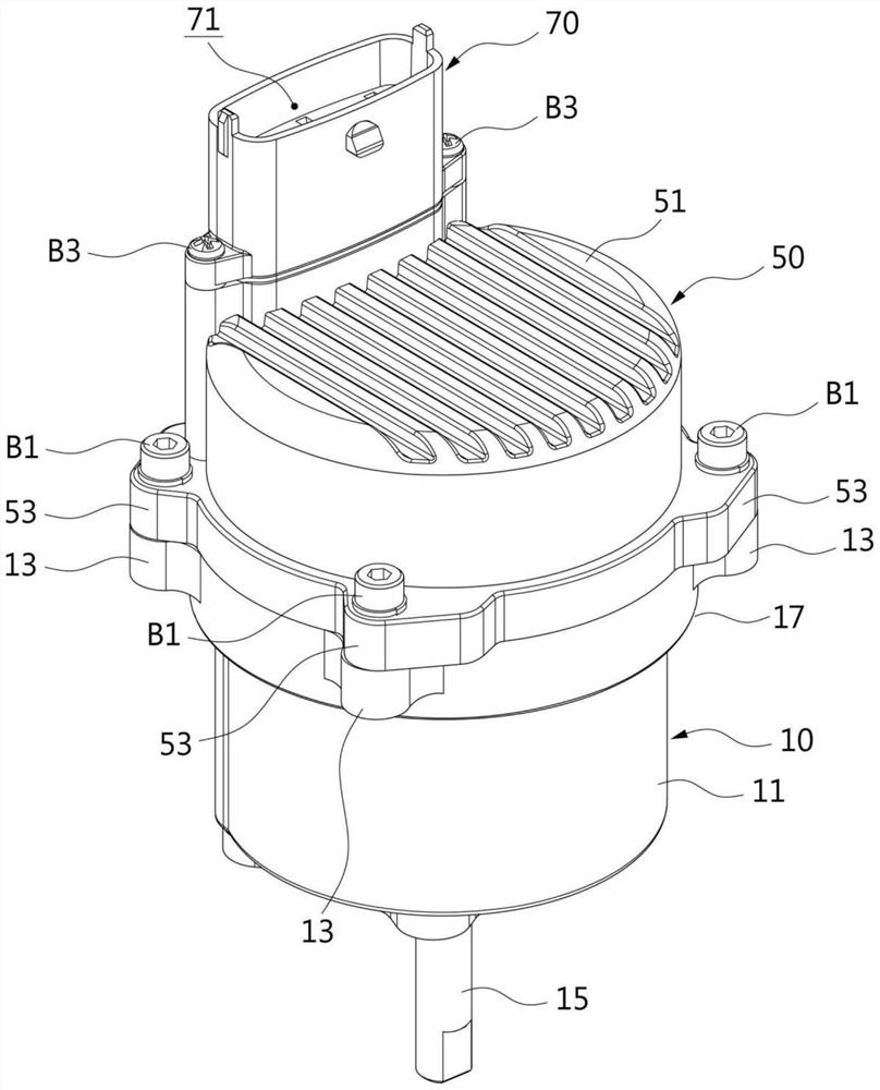
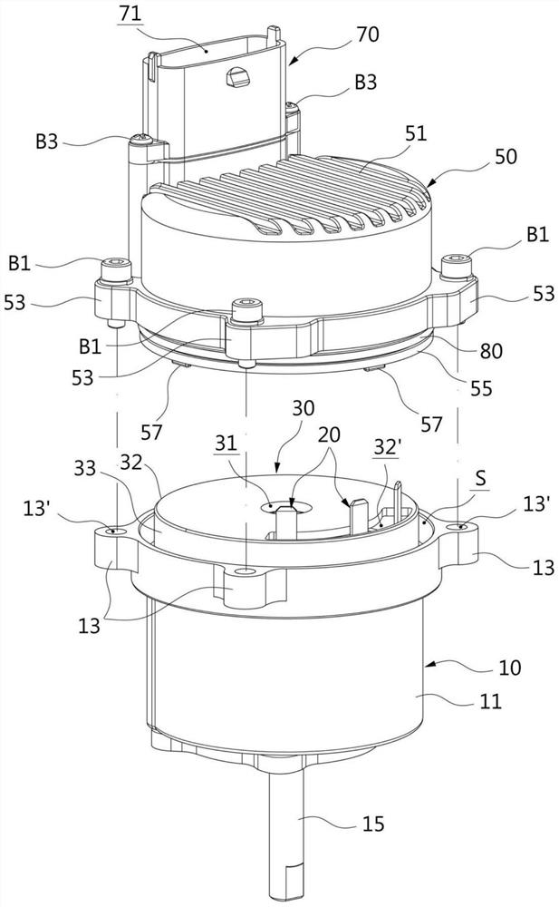
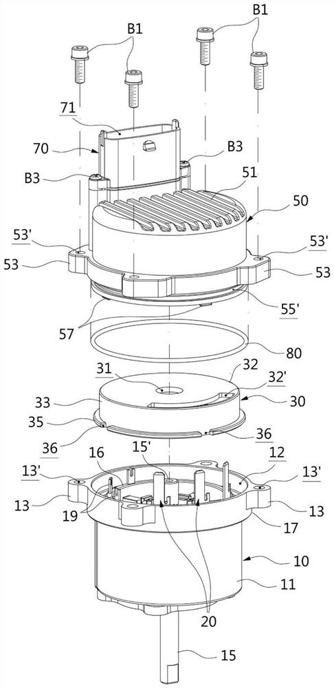
The invention relates to an electronic control module integrated motor assembly. The invention includes: a motor housing, a rotor and a stator are arranged in the motor space inside; a motor cover, combined with the motor housing to cover the upper part of the motor space; and a control module housing, which separates the motor The cover is coupled to the motor case, and a control space for installing a control unit for controlling the motor is formed inside the control module case. In addition, at least a part of the motor cover is located between the opposing edges of the motor housing and the control module housing, and when the motor housing and the control module housing are fastened by a fastening member, At least a portion of the motor cover is pressurized between the motor case and the control module case. In the motor assembly of the present invention, the motor cover is pressed between the motor housing and the control module housing to be securely fixed in the process of fastening the motor housing and the control module housing.

Description

technical field [0001] The present invention relates to a motor assembly, more particularly to an integrated motor assembly in which a controller is directly combined with the motor. Background technique [0002] A motor for generating rotational force includes a rotor and a stator (stator) inside, and generates rotational force by rotating the rotor with an electric current supplied from the outside. Such a motor can be connected to an electronic control unit (Eelectronic Control Unit, ECU), and the motor can be controlled in various ways through the electronic control unit. For example, an electronic control unit can turn a motor on according to a certain signal, or turn the motor on or off only when certain conditions are met. [0003] Such an electronic control unit is usually arranged separate from the motor and is connected by a cable. Therefore, it may be considered that the motor and the electronic control unit may be integrated due to difficulties in setup and man...

Claims


Application Information

Patent Timeline
Patent Type & Authority Patents(China)
IPC IPC(8): H02K11/30H02K5/04
CPCH02K11/30H02K5/04H02K2211/03H02K5/10H02K5/225
Inventor 金会千
Owner KEYANG ELECTRIC MACHINERY
Learn More