Simple cyclic shearing instrument of rock mass structure surfaces, and simple cyclic shearing test method of rock mass structure surfaces
A technology of structural surface and shear instrument, applied to shear anisotropy test of rock mass structural surface and surrounding rock lining contact surface, simple cyclic shear test of rock mass structural surface, simple cyclic shear instrument of rock mass structural surface field, which can solve problems such as inconvenient operation
- Summary
- Abstract
- Description
- Claims
- Application Information
AI Technical Summary
Problems solved by technology
Method used
Image
Examples
Embodiment 1
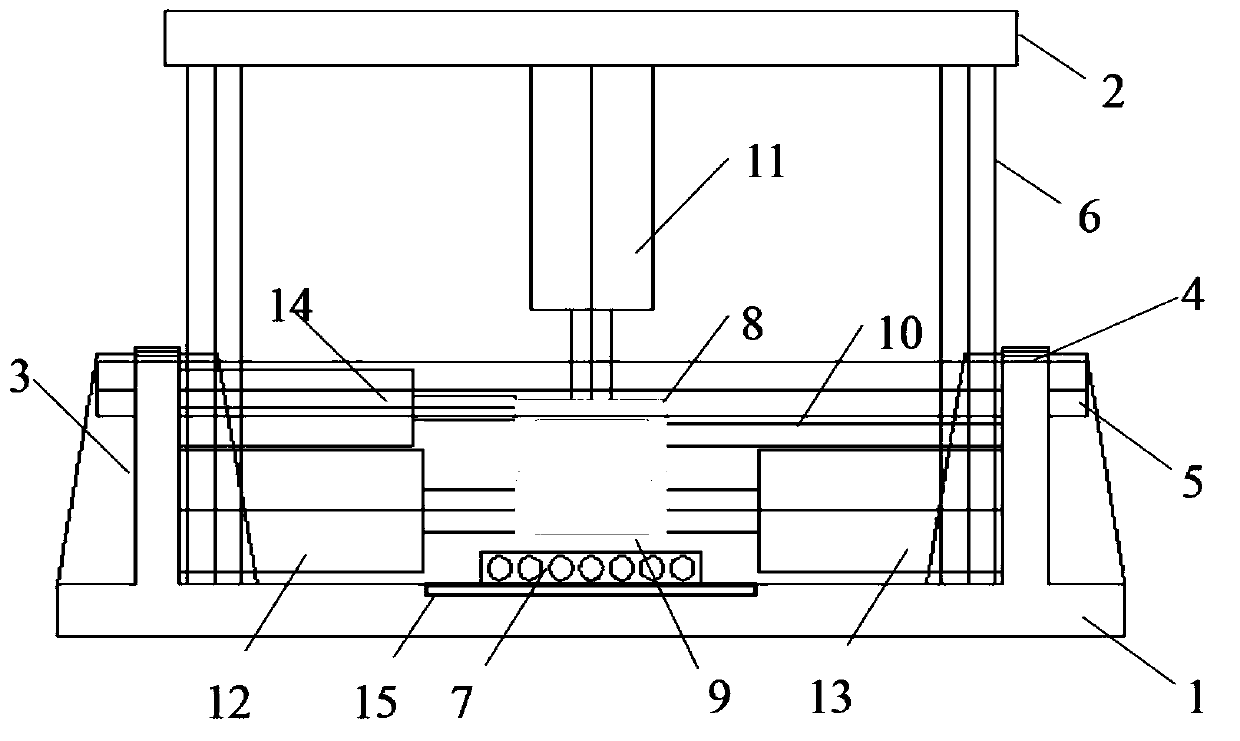
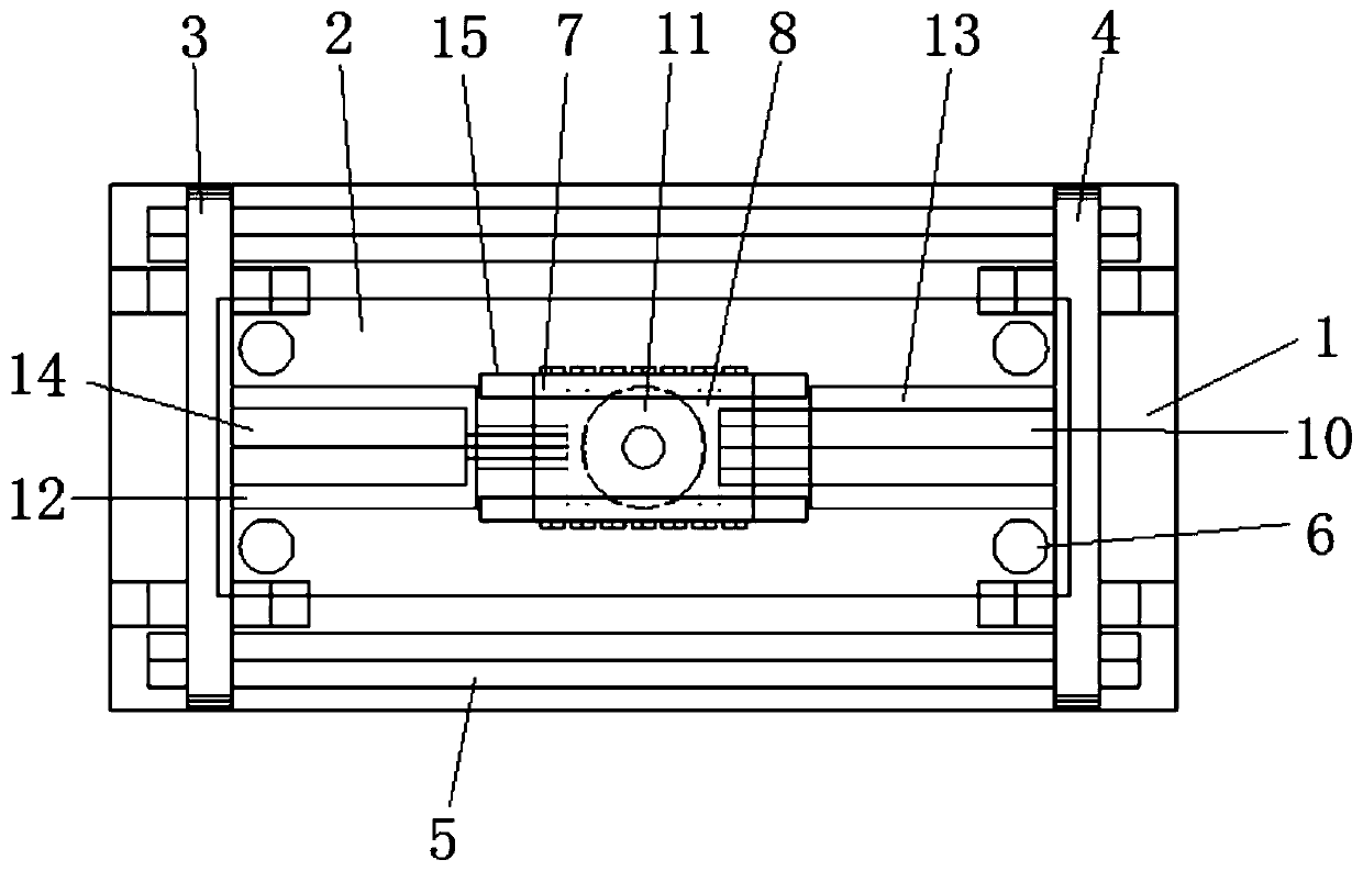
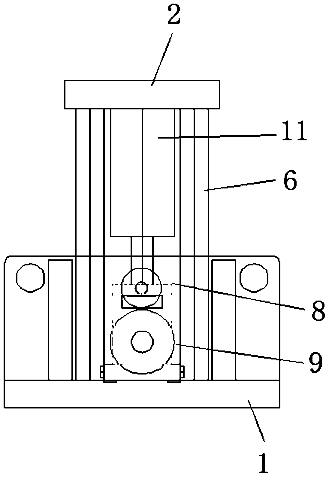
[0036] A simple circular shearing instrument for a rock mass structural surface, comprising a fixed base plate 1, a first side plate 3 and a second side plate 4 are arranged on the fixed base plate 1, a slide plate 7 is placed on the fixed base plate 1, and the slide plate 7 is located on the first side Between the plate 3 and the second side plate 4, the lower shear box 9 is arranged on the slide plate 7, the upper shear box 8 is located above the lower shear box 9, the fixing seat of the fixed jack 14 is connected with the first side plate 3, fixed The telescopic end of the jack 14 abuts against one side of the upper shear box 8, the other opposite side of the upper shear box 8 abuts against one end of the retaining column 10, the other end of the retaining column 10 is connected with the second side plate 4, and the first tangential jack 12 The fixed base of the first side plate 3 is fixed, the telescopic end of the first tangential jack 12 is offset against one side of the ...
Embodiment 2
[0043] Utilize the simple cyclic shear instrument of rock mass structural surface described in embodiment 1 to carry out the cyclic shear test method of rock mass structural surface. Include the following steps:
[0044] Step 1. Process the rock blocks with structural planes collected on site into rock mass structural plane samples of 150×150×150 mm, and place the rock mass structural plane in the middle of the rock mass structural plane samples;
[0045] Step 2, put the rock mass structural surface sample into the upper shear box 8 and the lower shear box 9, the bottom of the rock mass structural surface sample is set in the lower shear box 9, and the upper shear box 8 is fastened on the rock mass At the top of the structural surface sample, the distance between the uppermost side of the rock mass structural surface and the bottom edge of the upper shear box 8 is 5 mm to 10 mm, and the distance between the lowermost side of the rock mass structural surface and the top edge of t...
Embodiment 3
[0052] Utilize the rock mass discontinuity surface simple and easy circular shear instrument that embodiment 1 records to carry out the shear anisotropy test method of rock mass discontinuity surface and surrounding rock-lining contact surface.
[0053] Step 1. Through three-dimensional scanning and 3D printing technology, a batch of samples with the same appearance and material parameters are restored and produced. The samples are rock mass structural surface samples or surrounding rock lining contact surface samples. The size of each sample is They are all square specimens of 150×150×150 mm in size. The rock mass structural surface or the surrounding rock lining contact surface is placed in the middle of the sample, and the rock mass structural surface or surrounding rock lining contact surface is uniformly marked on the left and right sides of the sample.
[0054] Step 2, put the sample into the upper shear box 8 and the lower shear box 9, the bottom of the sample is set in ...
PUM
 Abstract
Description
Claims
Application Information
 - R&D
- Intellectual Property
- Life Sciences
- Materials
- Tech Scout
- Unparalleled Data Quality
- Higher Quality Content
- 60% Fewer Hallucinations
Browse by: Latest US Patents, China's latest patents, Technical Efficacy Thesaurus, Application Domain, Technology Topic, Popular Technical Reports.
© 2025 PatSnap. All rights reserved.Legal|Privacy policy|Modern Slavery Act Transparency Statement|Sitemap|About US| Contact US: help@patsnap.com


