Oil-containing wastewater treatment process combining ultrafiltration membrane and electro-catalysis method

A wastewater treatment and ultrafiltration membrane technology, which is applied in the direction of neutralization water/sewage treatment, water/sewage treatment, water/sewage multi-stage treatment, etc., can solve the problem of emulsified oil and cutting oil wastewater, and the removal effect is not ideal , Poor biodegradability and other problems, to achieve the effect of improved treatment effect, easy automation, and low filtration resistance

Inactive Publication Date: 2019-09-13
JIUPEI SUZHOU ENVIRONMENTAL PROTECTION TECH CO LTD
View PDF4 Cites 2 Cited by
  • Summary
  • Abstract
  • Description
  • Claims
  • Application Information

AI Technical Summary

Problems solved by technology

Oily wastewater has the characteristics of easy emulsification, refractory degradation, and poor biodegradability. The traditional treatment process currently used is not easy to meet the standard.
Such as oil separation method, flotation method and centrifugal separation method, etc., basically target free oil and suspended solids in wastewater, and the removal effect on wastewater containing emulsified oil and cutting oil is not ideal
[0003] The traditional electrocatalytic method directly degrades organic matter through anodic reaction or generates oxidants such as hydroxyl radicals, OH, and 02 to degrade organic matter. The strong oxidant produced at the anode oxidizes organic pollutants and microbial organisms in wastewater, which can basically meet the process requirements. Some emulsified oil and cutting oil wastewater are not treated well, which causes a great load on the subsequent treatment

Method used


Image

  • Oil-containing wastewater treatment process combining ultrafiltration membrane and electro-catalysis method

Examples


Embodiment

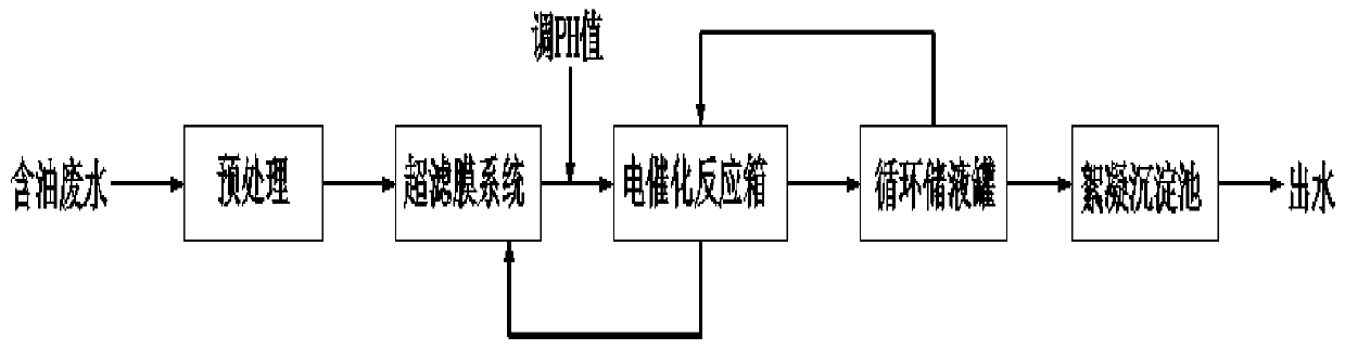
[0021] The oily wastewater treatment process combining ultrafiltration membrane and electrocatalysis includes the following steps:

[0022] Step 1. Pre-treat the wastewater containing emulsion;

[0023] Step 2. Input the wastewater into the ultrafiltration membrane system for cross-flow filtration to concentrate the grease components, suspended solids and other macromolecular substances in it, so that the volume of the waste liquid is greatly reduced; the residence time of the wastewater in the ultrafiltration membrane system is 3~5min.

[0024] Step 3. Input the effluent of the ultrafiltration membrane system into the electrocatalytic reaction box, adjust the Ph value, add activated carbon, and perform the electrocatalytic oxidation reaction; the residence time of the wastewater in the electrocatalytic reaction box is 10 minutes.

[0025] Step 4. The effluent of the electrocatalytic reaction box is divided into two parts, the upper clear liquid is returned to the circulating liquid s...


PUM

PropertyMeasurementUnit
pore sizeaaaaaaaaaa
porosityaaaaaaaaaa

Abstract

The invention discloses an oil-containing wastewater treatment process combining an ultrafiltration membrane and an electro-catalysis method. The process comprises the following steps: (1) pretreatingemulsion-containing wastewater; (2) inputting the wastewater into an ultrafiltration membrane system, performing cross-flow filtration, and concentrating grease components, suspended solid and othermacromolecular substances in the wastewater so as to reduce the volume of the waste liquid greatly; (3) inputting the effluent of the ultrafiltration membrane system into an electro-catalysis reactiontank, adjusting the pH value, adding activated carbon, and carrying out an electro-catalytic oxidation reaction; (4) dividing the effluent of the electro-catalysis reaction tank into two parts, returning the supernatant to a circulating liquid storage tank, returning the bottom turbid liquid to the ultrafiltration membrane system, and performing continuous circulation of the wastewater in the ultrafiltration membrane system, the electro-catalysis reaction tank and the circulating liquid storage tank; and (5) performing circulation of the above process for a certain period of time, inputting the effluent of the circulating liquid storage tank into a flocculation sedimentation tank, adjusting the pH value, adding chemicals, completing flocculation and sedimentation, and inputting the effluent to a subsequent treatment system.

Description

Technical field [0001] The invention relates to an oily wastewater treatment process combining an ultrafiltration membrane and an electrocatalytic method. Background technique [0002] A large amount of oily emulsion wastewater is produced in steel, machinery and other industries, and its composition is relatively complex, mainly containing mineral oil, fatty acid surfactants, suspended impurities, emulsifiers, and lubricants. Oily wastewater has the characteristics of easy emulsification, difficult degradation, and poor biodegradability, and the traditional treatment technology currently used is not easy to meet the standard. For example, oil separation method, flotation method and centrifugal separation method are basically based on the removal of free oil and suspended solids in wastewater, and the removal effect of wastewater containing emulsified oil and cutting oil is not ideal. [0003] The traditional electrocatalytic method directly degrades organic matter through anode r...

Claims


Application Information

Patent Timeline
Patent Type & Authority Applications(China)
IPC IPC(8): C02F9/06
CPCC02F1/444C02F1/4672C02F1/52C02F1/66C02F9/00
Inventor 禹久泓杨名许县明
Owner JIUPEI SUZHOU ENVIRONMENTAL PROTECTION TECH CO LTD
Why Eureka
Try Eureka