
Mounting structure of rotor iron core and magnetic steel

A technology of mounting structure and rotor core, applied in the direction of magnetic circuit shape/style/structure, magnetic circuit, electromechanical device, etc., can solve the problems of increasing the manufacturing cost of tooling, affecting the production efficiency of the workshop, and not improving the efficiency, so as to achieve saving Cost, facilitate assembly, and improve installation efficiency

Pending Publication Date: 2019-09-10
KINETEK DE SHENG SHUNDE MOTOR CO LTD
View PDF0 Cites 1 Cited by
  • Summary
  • Abstract
  • Description
  • Claims
  • Application Information

AI Technical Summary

Problems solved by technology

This problem affects the production efficiency of the workshop, and also brings a lot of inconvenience to the workers
In order to solve the above problems, many motor manufacturers can only make tooling corresponding to punches of various shapes, so that workers can guide the magnetic steel into the slot of the rotor core, which not only increases the manufacturing cost of the tooling, but also does not improve the efficiency. improve, need further improvement

Method used


Image

  • Mounting structure of rotor iron core and magnetic steel
  • Mounting structure of rotor iron core and magnetic steel
  • Mounting structure of rotor iron core and magnetic steel

Examples


Embodiment 1

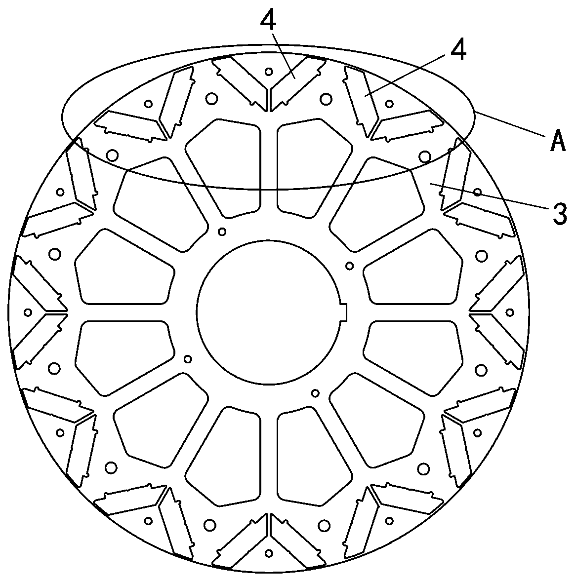
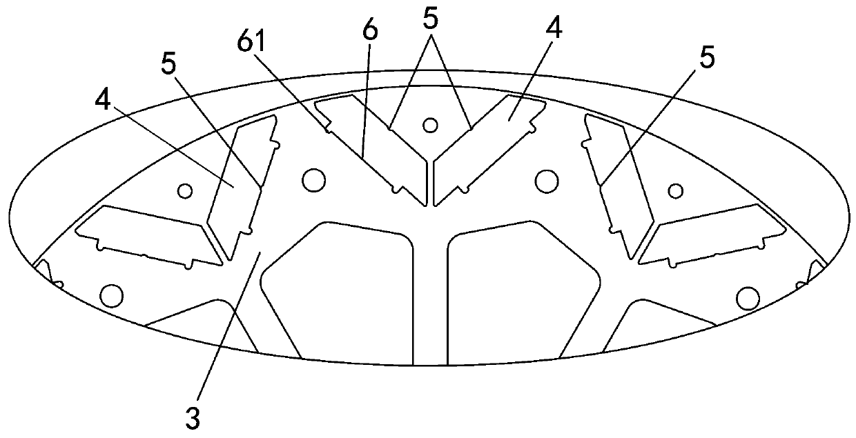
[0022] Embodiment one, see Figure 1 to Figure 5 As shown, a rotor core and magnetic steel installation structure includes a magnetic steel 2 and a rotor core 1 laminated by rotor punches 3, and a number of through holes 4 are evenly distributed on the rotor punches 3, through which The hole 4 is arranged in a ring on the outer peripheral edge of the rotor punching plate 3. The through hole 4 is similar to an isosceles trapezoidal shape, and two through holes 4 form a group. The through holes 4 in each group are symmetrically arranged on the left and right, and form a V shape. , the lower bottom of the through hole 4 is provided with an open slot 6, and the two ends of the bottom of the open slot 6 are respectively provided with a U-shaped slot 61. After the rotor core 1 is formed by stacking the rotor punches 3, the corresponding through hole 4 forms a magnetic steel installation hole. 20 , the magnet steel 2 is inserted into the magnet steel installation hole 20 .

[0023] ...


PUM


Abstract

The invention discloses a mounting structure of a rotor iron core and magnetic steel. The mounting structure comprises the magnetic steel and the rotor iron core formed by laminating a rotor punchingsheet, and is characterized in that through holes are uniformly distributed in the rotor punching sheet; after the rotor punching sheet is laminated into the rotor iron core, a magnetic steel mountinghole is formed by corresponding through holes; the magnetic steel is inserted into the magnetic steel mounting hole; and the side surface where the magnetic steel N pole / S pole is located and the side surface wherein the N pole / S pole of the magnetic steel mounting hole is located are matched through a concave-convex structure. The mounting structure is reasonable in design, and protruding blocksand opening grooves of the through holes are used for positioning and guiding the magnetic steel, so that the magnetic steel is conveniently guided into the magnetic steel mounting hole; meanwhile, the through holes are matched with the grooves of the magnetic steel through convex strips in a concave-convex mode, so that the mounting direction of the N pole / S pole of the magnetic steel is limited, the magnetic pole direction of the magnetic steel is prevented from being mounted incorrectly, the mounting efficiency of the magnetic steel is improved, and the cost of manufacturing a magnetic steel mounting tool is also saved; and the convex blocks and the grooves adopt arc design, so that assembling can be facilitated, and the operation is safer.

Description

technical field [0001] The invention relates to the technical field of motors, in particular to a mounting structure for a rotor iron core and magnetic steel. Background technique [0002] In the motor manufacturing process, putting magnetic steel in the rotor core has always been a problem that has plagued the workshop. Under the strong magnetic force, it is not only necessary to ensure that the magnetic steel can be completely guided into the notch of the rotor core, but also to ensure that the N and S poles of the magnetic steel are in the correct orientation position in the rotor. This problem affects the production efficiency of the workshop, and also brings a lot of inconvenience to the workers' operations. In order to solve the above problems, many motor manufacturers can only make tooling corresponding to punches of various shapes, so that workers can guide the magnetic steel into the slot of the rotor core, which not only increases the manufacturing cost of the too...

Claims


Application Information

Patent Timeline
Patent Type & Authority Applications(China)
IPC IPC(8): H02K1/27
CPCH02K1/2766
Inventor 孙显旺曾国辉何茂兴
Owner KINETEK DE SHENG SHUNDE MOTOR CO LTD
Learn More