
Thin-wall part robot machining path generation method based on machining parameters

A technology for robot processing and thin-walled parts, applied in the direction of instruments, digital control, program control, etc., can solve the problems of calculating the machining allowance from the design model and restricting the application of robots, etc. Effect

Active Publication Date: 2019-09-10
HUAZHONG UNIV OF SCI & TECH
View PDF7 Cites 2 Cited by
  • Summary
  • Abstract
  • Description
  • Claims
  • Application Information

AI Technical Summary

Problems solved by technology

[0003] At the present stage, robot machining paths are mostly generated based on the design model, which is similar to the method of NC machining trajectory generation. However, for thin-walled parts with small curvature, there may be a large gap between the actual blank and the design model, and due to the existence of manufacturing and assembly errors, it is necessary to A certain process allowance is reserved in the part blank processing stage for repairing, so it is difficult to calculate the corresponding machining allowance and generate the corresponding processing trajectory according to the design model, which limits the application of robot processing

Method used


Image

  • Thin-wall part robot machining path generation method based on machining parameters
  • Thin-wall part robot machining path generation method based on machining parameters
  • Thin-wall part robot machining path generation method based on machining parameters

Examples


Embodiment Construction

[0036] In order to make the object, technical solution and advantages of the present invention clearer, the present invention will be further described in detail below in conjunction with the accompanying drawings and embodiments. It should be understood that the specific embodiments described here are only used to explain the present invention, not to limit the present invention. In addition, the technical features involved in the various embodiments of the present invention described below can be combined with each other as long as they do not constitute a conflict with each other.

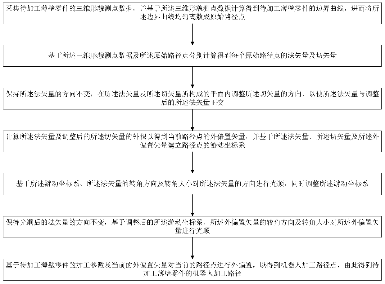
[0037] see figure 1 , figure 2 and image 3 , the method for generating a machining path of a thin-walled part robot based on processing parameters provided by the present invention, the method is suitable for the generation of a milling path for a small-curvature thin-walled part, which includes the following steps:

[0038] Step 1, collecting the three-dimensional shape measuring point dat...


PUM


Abstract

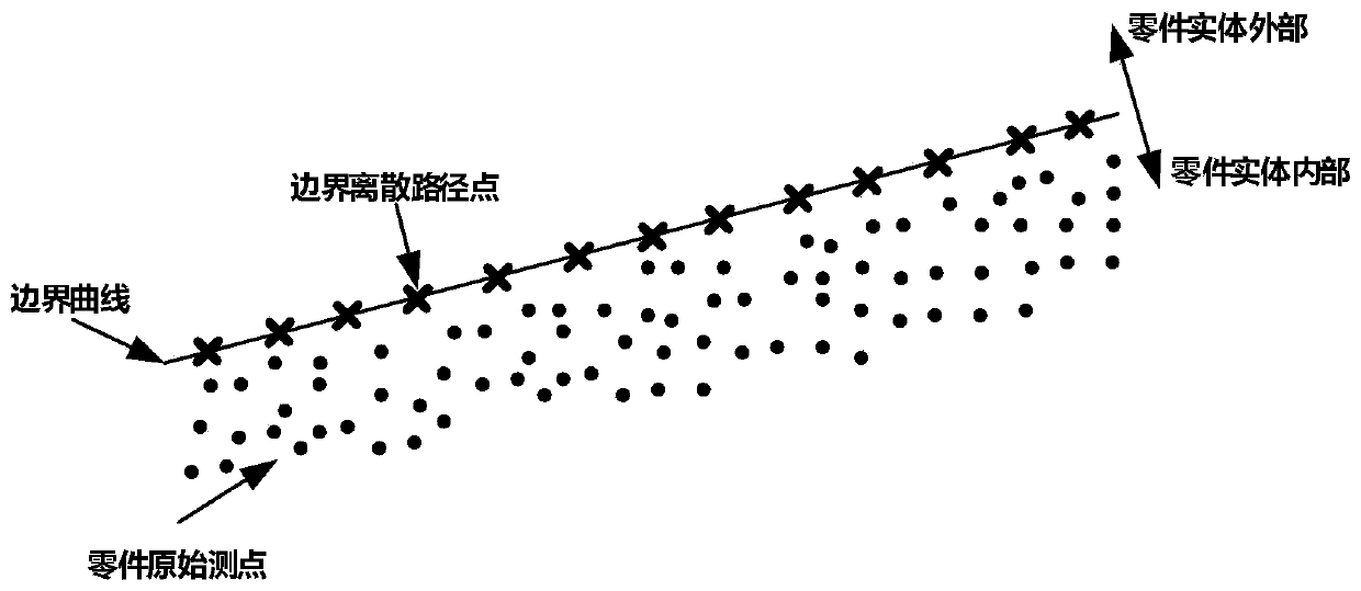
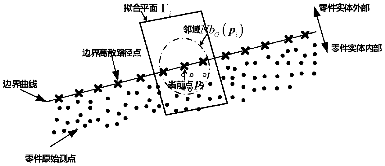
The invention belongs to the relevant technical field of path generation, and discloses a thin-wall part robot machining path generation method based on machining parameters. The method comprises thefollowing steps of (1) uniformly dispersing the boundary curve of a thin-wall part to be processed into original path points; (2) respectively calculating to obtain a normal vector and a tangent vector of each original path point; (3) wherein the normal vector and the tangent vector are orthogonal; (4) calculating the outer product of the normal vector and the tangent vector to obtain the outer offset vector of the current path point, and establishing a moving coordinate system of the path point based on the normal vector, the tangent vector and the outer offset vector; (5) smoothing the direction of the normal vector based on the moving coordinate system, and simultaneously adjusting the moving coordinate system; (6) smoothing the outer bias vector based on the corner direction and the corner size of the outer bias vector; and (7) performing external offset on the path point to obtain a robot machining path of the thin-wall part to be processed. The thin-wall part robot machining pathgeneration method based on machining parameters is easy to implement and has stronger applicability.

Description

technical field [0001] The invention belongs to the technical field related to path generation, and more specifically relates to a method for generating a machining path of a thin-walled part robot based on machining parameters. Background technique [0002] It has become one of the cutting-edge research directions in the field of intelligent manufacturing to use robots as the execution body of manufacturing equipment, integrate intelligent sensors, and replace human manual or CNC machine tools to realize small margin milling, grinding, hole making, drilling and riveting of large and complex parts. Thin-walled parts with small curvature often have a certain processing allowance due to their processing and molding process and the requirements of later assembly. A certain process allowance is used for trimming and cutting with adjacent skins during assembly. At present, manual grinding is often used to remove the allowance of thin-walled parts with small curvature. The proces...

Claims


Application Information

Patent Timeline
Patent Type & Authority Applications(China)
IPC IPC(8): G05B19/19
CPCG05B19/19G05B2219/35092
Inventor 李文龙蒋诚彭泽龙王刚
Owner HUAZHONG UNIV OF SCI & TECH
Learn More