System control method and device
A control method and controller technology, applied in the field of communication, can solve problems such as low control accuracy, and achieve the effects of avoiding large errors, precise control, and solving low control accuracy
- Summary
- Abstract
- Description
- Claims
- Application Information
AI Technical Summary
Problems solved by technology
Method used
Image

Examples
Embodiment 1
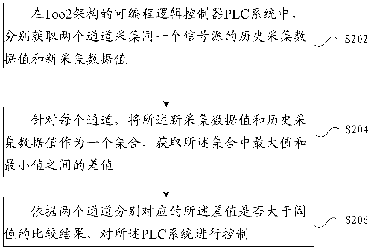
[0021] In this embodiment, a system control method running on a PLC system is provided, figure 2 is a flowchart of a system control method according to an embodiment of the present application, such as figure 2 As shown, the process includes the following steps:
[0022] Step S202, in the PLC system with 1oo2 architecture, respectively obtain the historical collection data value and the new collection data value of the same signal source collected by two channels;
[0023] The subject of execution of the method may be the first controller, and the first controller may be a master controller or a slave controller corresponding to the dual channels,
[0024] Step S204, for each channel, use the new collected data value and the historical collected data value as a set, and obtain the difference between the maximum value and the minimum value in the set;
[0025] Step S206, controlling the PLC system according to a comparison result of whether the difference corresponding to t...
Embodiment 2
[0058] In this embodiment, a system control device is also provided, which is used to implement the above embodiments and preferred implementation modes, and what has been explained will not be repeated here. As used below, the term "module" may be a combination of software and / or hardware that realizes a predetermined function. Although the devices described in the following embodiments are preferably implemented in software, implementations in hardware, or a combination of software and hardware are also possible and contemplated.
[0059] According to another embodiment of the present application, a system control device is also provided, which is used in a PLC system with 1oo2 architecture, including:
[0060] The first acquisition module is used to respectively acquire the historical acquisition data value and the new acquisition data value of the same signal source acquired by the two channels;
[0061] The second acquisition module is configured to use the newly collect...
Embodiment 3
[0068] The embodiment of the present application also provides a storage medium. Optionally, in this embodiment, the above-mentioned storage medium may be configured to store program codes for performing the following steps:
[0069] S1, in the programmable logic controller PLC system with 1oo2 architecture, respectively obtain the historical collection data value and the new collection data value of the same signal source collected by two channels;
[0070] S2. For each channel, use the newly collected data value and the historically collected data value as a set, and obtain the difference between the maximum value and the minimum value in the set;
[0071] S3. Control the PLC system according to a comparison result of whether the difference corresponding to the two channels is greater than a threshold.
[0072] Optionally, in this embodiment, the above-mentioned storage medium may include but not limited to: U disk, read-only memory (ROM, Read-Only Memory), random access me...
PUM
 Abstract
Description
Claims
Application Information
 - R&D
- Intellectual Property
- Life Sciences
- Materials
- Tech Scout
- Unparalleled Data Quality
- Higher Quality Content
- 60% Fewer Hallucinations
Browse by: Latest US Patents, China's latest patents, Technical Efficacy Thesaurus, Application Domain, Technology Topic, Popular Technical Reports.
© 2025 PatSnap. All rights reserved.Legal|Privacy policy|Modern Slavery Act Transparency Statement|Sitemap|About US| Contact US: help@patsnap.com