
Vehicle center line calibration method and system

A calibration system and centerline technology, applied in the vehicle centerline calibration method and system field, can solve problems such as large measurement errors, errors caused by elastic deformation of tape measures, and observation angle errors, so as to reduce labor costs, avoid large errors, and ensure The effect of accuracy

Pending Publication Date: 2022-04-15
XIANGYANG DAAN AUTOMOBILE TEST CENT
View PDF0 Cites 0 Cited by
  • Summary
  • Abstract
  • Description
  • Claims
  • Application Information

AI Technical Summary

Problems solved by technology

[0002] Passenger cars are being tested, and it is necessary to calibrate the centerline Y0 of the vehicle body parked horizontally. Take two points on the centerline Y0 above the roof, and the distance between the two points is 0.98M. In the actual operation process, the problem of excessive measurement error is mainly reflected in the fact that when the body has only one fixed hard point for calibration, since the body is curved, the section of the tape is also curved. During the measurement, the elastic deformation of the tape and the curved surface of the body will be too large. Error; For the hard points of the vehicle body, it is impossible to measure the high-precision centerline Y0 with a tape measure or a laser rangefinder, because the vehicle cab blocks the hard points at the front and rear of the vehicle body
In addition, during the measurement process, if the measurer's body posture is constantly adjusted with the height of the vehicle, the change of the observation angle will cause errors

Method used


Image

  • Vehicle center line calibration method and system
  • Vehicle center line calibration method and system
  • Vehicle center line calibration method and system

Examples


Embodiment Construction

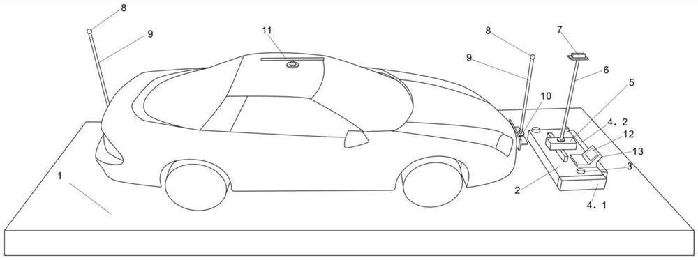
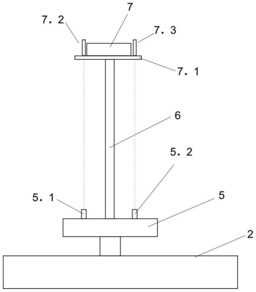
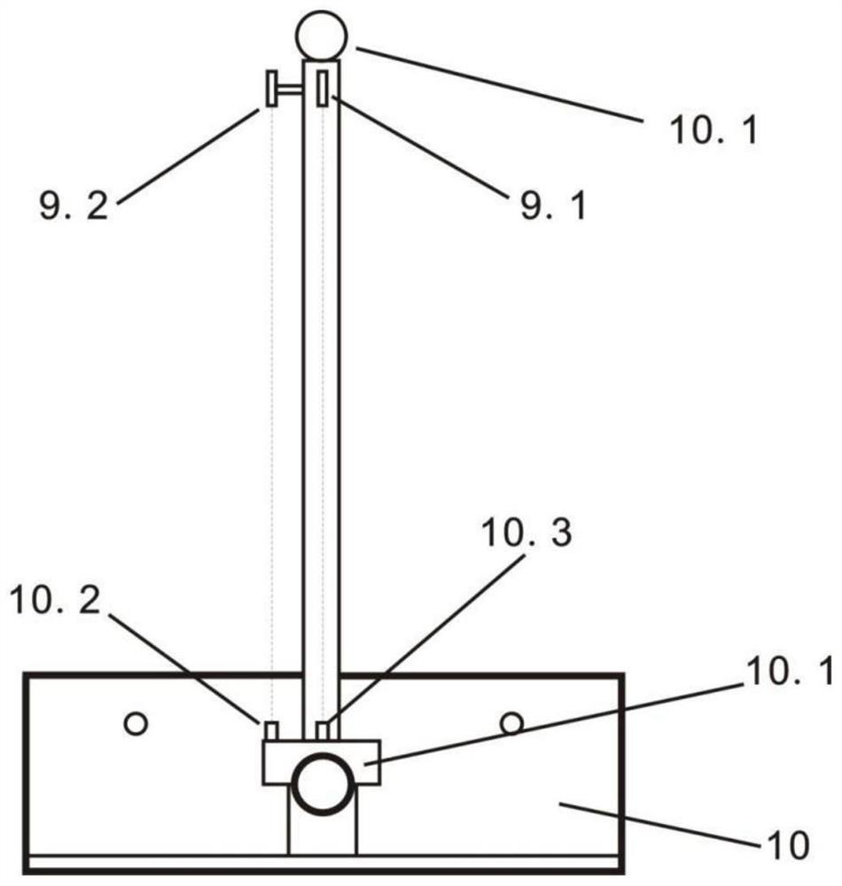
[0060] figure 1 Among them, the system for demarcating the center line of the vehicle of the present invention includes a vehicle reference device, a vehicle attitude detection device, a calibration device, and a controller 12; the vehicle reference device includes a front reference device and a rear reference device with the same structure, and The reference device is installed in the front and rear license plate frames of the vehicle to be calibrated, and is used to obtain the reference center line Y0 of the vehicle through two points; the vehicle to be calibrated is located on the preset metal platform 1, and the function of the vehicle attitude detection device is to automatically move and lift Look for the hard points protruding vertically from the front reference device and the rear reference device on the license plate frame of the vehicle body. The vehicle posture detection device includes the body support 2, and the body support 2 is provided with one end of the metal ...


PUM


Abstract

The invention relates to a calibration system and a calibration method for a vehicle center line. The calibration system for the vehicle center line comprises a vehicle datum reference device, a vehicle attitude detection device, a calibration device and a data processor, wherein the data processor is used for obtaining a vehicle deviation angle according to a numerical value measured by a laser scanning ranging radar; the vehicle datum reference device comprises a front reference device and a rear reference device which are arranged in front and rear license plate frames of a to-be-calibrated vehicle; the center connecting line of the metal balls of the front reference device and the rear reference device and the datum center line Y0 of the vehicle are located on the same vertical plane. The vehicle posture detection device comprises a body support, a two-axis sliding table which is installed on the body support and can slide in the X-axis direction and the Y-axis direction of the body support, an electric telescopic rod erected on the two-axis sliding table, and a fine adjustment platform installed at the top end of the electric telescopic rod. The laser scanning range radar is arranged on the fine tuning platform; the calibration device comprises a three-axis calibration rod, a height measuring device and a guiding rule. Labor cost is reduced, and calibration efficiency and calibration precision are improved.

Description

technical field [0001] The invention relates to the technical field of vehicle detection, in particular to a calibration method and system for a vehicle centerline. Background technique [0002] Passenger cars are being tested, and it is necessary to calibrate the centerline Y0 of the vehicle body parked horizontally. Take two points on the centerline Y0 above the roof, and the distance between the two points is 0.98M. In the actual operation process, the problem of excessive measurement error is mainly reflected in the fact that when the body has only one fixed hard point for calibration, since the body is curved, the section of the tape is also curved. During the measurement, the elastic deformation of the tape and the curved surface of the body will be too large. Error: For the hard points of the vehicle body, it is impossible to measure the high-precision centerline Y0 with a tape measure or a laser rangefinder, because the vehicle cab blocks the hard points at the front...

Claims


Application Information

Patent Timeline
IPC IPC(8): G01B21/24G01M17/007
Inventor 刘登明姜晓来刘阳刘杰潘鹏
Owner XIANGYANG DAAN AUTOMOBILE TEST CENT
Learn More