Quake sourcepositioning method and device based on three-dimensional velocity model and storage medium

A velocity model and source location technology, applied in measurement devices, seismology, seismic measurement, etc., can solve the problems of wave velocity inhomogeneity, the accuracy of the source location is difficult to meet the application requirements, and the time pickup error, etc., to improve the location accuracy. Effect

Inactive Publication Date: 2019-09-10
CENT SOUTH UNIV +1
View PDF3 Cites 8 Cited by
  • Summary
  • Abstract
  • Description
  • Claims
  • Application Information

AI Technical Summary

Problems solved by technology

[0003] In actual three-dimensional positioning, the accuracy of seismic source positioning is difficult to meet the application requirements due to the large number of sensors, non-uniform wave velocity, time picking error, and non-point source of the seismic source.

Method used


Image

  • Quake sourcepositioning method and device based on three-dimensional velocity model and storage medium
  • Quake sourcepositioning method and device based on three-dimensional velocity model and storage medium
  • Quake sourcepositioning method and device based on three-dimensional velocity model and storage medium

Examples


Embodiment Construction

[0048] The technical solutions of the present invention will be further described in detail below in conjunction with the drawings and specific embodiments of the description. It should be understood that the examples provided here are only used to explain the present invention, not to limit the present invention. In addition, the examples provided below are some examples for implementing the present invention, rather than providing all the examples for implementing the present invention. In the case of no conflict, the technical solutions recorded in the embodiments of the present invention can be combined in any manner implement.

[0049] Unless otherwise defined, all technical and scientific terms used herein have the same meaning as commonly understood by one of ordinary skill in the technical field of the invention. The terms used herein in the description of the present invention are for the purpose of describing specific embodiments only, and are not intended to limit ...


PUM


Abstract

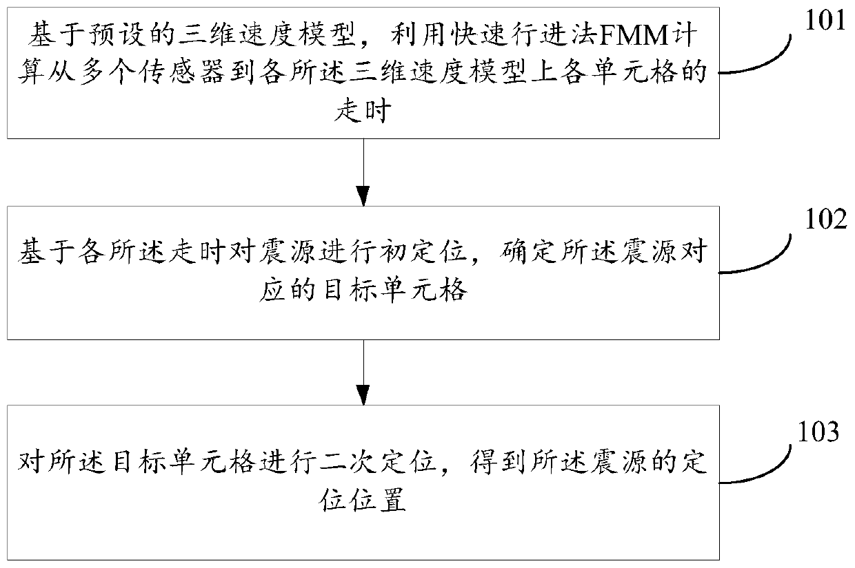
The invention discloses a quake source positioning method and device based on a three-dimensional velocity model and a storage medium.The quake source positioning method comprises the steps that timetravel from a plurality of sensors to each cell of each three-dimensional velocity model is calculated by using a fast marching method (FMM) based onthe preset three-dimensional velocity model;a quakesource is initially positionedbased on each of the travel times, and the target cell corresponding to the quake sourceis determined; and the target cell is secondarily positionedto obtain the positionedlocation of the quake source. Compared with an existing positioning algorithm, the accuracy of the quake sourcepositioning is effectively improved.

Description

technical field [0001] The invention relates to the field of microseismic monitoring, in particular to a seismic source location method, device and storage medium based on a three-dimensional velocity model. Background technique [0002] Microseismic location is the process of locating the source based on elastic waves generated by microseismic events, in which the elastic waves continue to extend outward to form a circular wave front (during wave propagation, the surface formed by points with the same vibration phase is called for the wavefront). When performing microseismic positioning, use the position of each sensor as the center of the circle, and use the distance value obtained by multiplying the medium wave velocity by the travel time to draw a circle with a radius. Each circle will intersect at a point, which is the location of the microseismic source. [0003] In actual 3D positioning, the accuracy of seismic source positioning is difficult to meet the application ...

Claims


Application Information

Patent Timeline
Patent Type & Authority Applications(China)
IPC IPC(8): G01V1/00G01V1/28
CPCG01V1/288G01V2210/129G01V2210/65G01V1/01
Inventor 彭平安王李管张建国蒋元建何正祥
Owner CENT SOUTH UNIV
Why Eureka
Try Eureka