
Warmer

A technology for heaters and heat sinks, applied in the field of heaters, which can solve the problems of easy misuse, shrinkage, and exacerbation of heating problems of end heat sinks, etc., to achieve the effect of ensuring user experience and simple structure

Pending Publication Date: 2019-09-10
SHIJIAZHUANG GREE SMALL HOUSEHOLD ELECTRICAL APPLIANCES +1
View PDF2 Cites 0 Cited by
  • Summary
  • Abstract
  • Description
  • Claims
  • Application Information

AI Technical Summary

Problems solved by technology

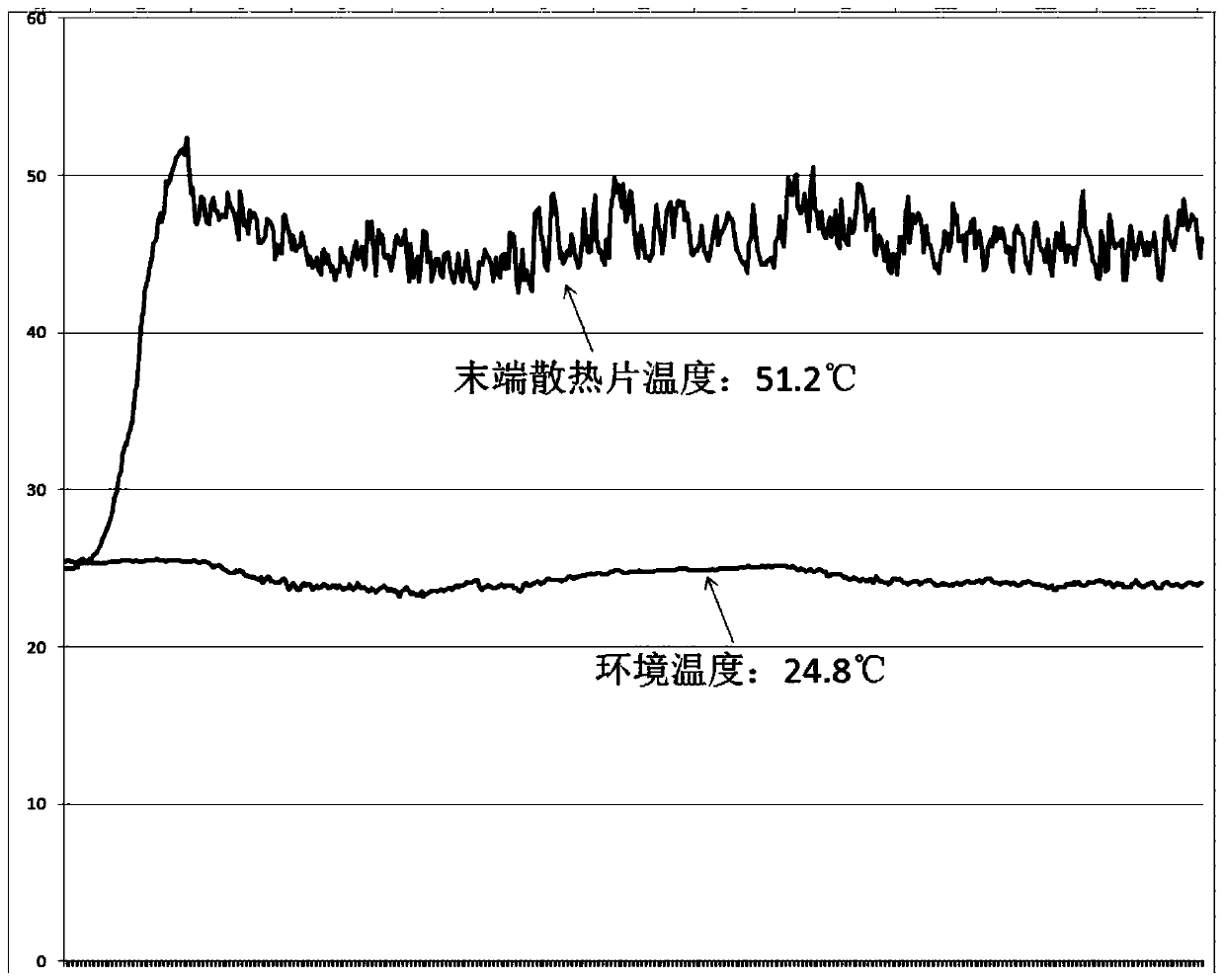
The temperature experimental data of the patent is as follows figure 1 As shown, the heater of the utility model does meet the requirement that the temperature rise of the accessible surface does not exceed 85K, but the upper / lower oil bags of the last heat sink are blocked, resulting in no heat transfer oil circulation in the last heat sink. The highest surface temperature rise is only 26.4K, and users report that the last piece does not heat up when heating, which leads to user complaints
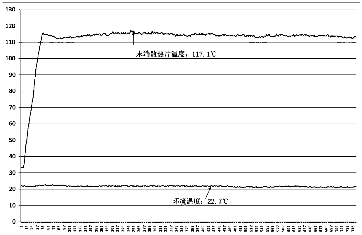
[0004] The existing patent application number is CN201210048144.5, and the patent name is an invention patent of a heater, which is provided with a flow blocking mechanism on the lower oil bag of the heat sink at the end, and an oil bag partition on the upper oil bag. In this patent, the heat dissipation at the end Although the oil clapboard of the heat sink is slightly higher than the oil clapboard of other heat sinks, since the flow of heat transfer oil is not strictly controlled, the heat transfer oil of other heat sinks can still flow into the end heat sink normally. And because the flow cross-sectional area of ​​the heat transfer oil is slightly reduced, the flow rate of the heat transfer oil may be further increased, which exacerbates the heating problem of the end heat sink. The temperature data of the end heat sink obtained by testing the heater of this patent is as follows: figure 2 As shown, the surface temperature rise of the heat sink at the end exceeds 85K, which cannot meet the requirements of the national standard, and the user is likely to accidentally touch it when using it and cause burns

Method used


Image

  • Warmer
  • Warmer
  • Warmer

Examples


Embodiment Construction

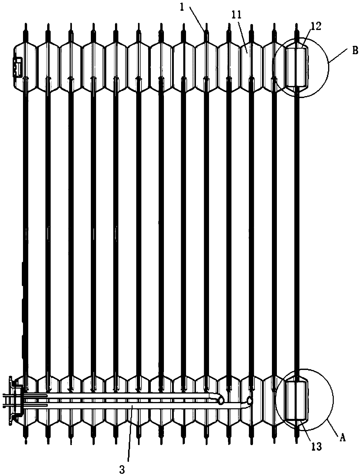
[0030] heater according to the present invention, such as image 3 As shown, it includes a heating device 3 and a plurality of heat sinks 1, each of which is provided with at least two oil storage chambers 11, and the oil storage chambers 11 in the same heat sink communicate with each other, so The plurality of cooling fins 1 are sequentially connected through the oil storage chamber 11 to form a circulation channel, the connection between the circulation channel and the oil storage chamber 11 is the circulation channel opening 14, and the heating device 3 is arranged in the circulation channel. In this embodiment, the first heat sink 1 or the last heat sink 1, or the first heat sink 1 and the last heat sink 1 of the plurality of heat sinks 1 connected in sequence are defined as end heat sinks.

[0031] Such as image 3 As shown, in the present invention, a flow limiting device 12 is provided in at least one oil storage cavity 11 of the end heat sink, and a flow blocking devi...


PUM


Abstract

The invention relates to the field of household appliances, in particular to a warmer. The warmer comprises multiple cooling fins, the multiple cooling fins sequentially communicate with one another through oil storing cavities to form a circulating channel, the joints of the circulating channel and the oil storing cavities are provided with circulating channel ports, the circulating channel areaof each circulating channel port is S, and each cooling fin is internally provided with at least two oil storing cavities; flow limiting devices are arranged in at least one oil storing cavity of theend cooling fins, flow blocking devices are arranged in at least one other oil storing cavity of the end cooling fins, the flow limiting devices comprise flow limiting structures, the flow limiting structures are used for limiting the circulating channel areas of the oil storing cavities of the adjacent cooling fins and the end cooling fins, and the flow blocking devices are used for isolating theoil storing cavities of the adjacent cooling fins from the oil storing cavities of the end cooing fins; and the circulating channel areas of the flow limiting structures are each between 0.1 S and 0.24 S. According to the warmer, it is guaranteed that a user can not be scalded due to accidental touching, and the using experience of the user is guaranteed.

Description

technical field [0001] The invention relates to the field of household appliances, in particular to a heater. Background technique [0002] Existing electric oil heating heaters usually circulate convectively along the heat sink through the heat conduction oil, and the heat is radiated out through the inner wall of the heat sink, thereby heating the space environment. However, the temperature of the back of the heater is very high, and it is easy for the user to accidentally touch it and be scalded when using it. In this regard, the national standard GB4706.23-2007 stipulates that the temperature rise of the metal surface that the heater will touch with the test rod should not exceed 85K. In order to reduce the back temperature of the heater, there are several methods commonly used at present: 1. Print a no-touch sign on the surface of the high-temperature oil circuit. Hidden dangers; 2. Reduce the power of the product. This method is highly safe, but reducing the power of...

Claims


Application Information

Patent Timeline
IPC IPC(8): F24D13/04F24D19/00
CPCF24D13/04F24D19/00F24D2200/08F24D2220/02
Inventor 李静苗立亚王霄鹏韩响周玲景盼
Owner SHIJIAZHUANG GREE SMALL HOUSEHOLD ELECTRICAL APPLIANCES
Learn More