
Connecting rod structure and engine

A connecting rod structure and connecting rod technology, applied in the field of vehicles, can solve the problems of inability to arrange connecting rod bolts, small wall thickness, and reduced rigidity of the large end of the connecting rod.

Inactive Publication Date: 2019-09-10
WEICHAI POWER CO LTD
View PDF5 Cites 1 Cited by
  • Summary
  • Abstract
  • Description
  • Claims
  • Application Information

AI Technical Summary

Problems solved by technology

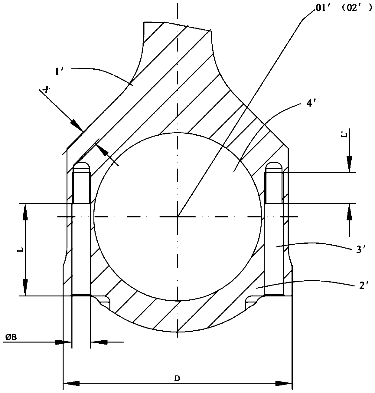
[0005] like image 3 As shown, with this arrangement, the counterbore section L of the connecting rod bolt hole 3' needs to be greater than the height of the connecting rod cover 2', and cross the divided contact surface 01'3mm-5mm. At the same time, in order to ensure that the connecting rod bolt hole 3' The threaded section has enough thread engagement length L', which will cause the wall thickness X between the connecting rod bolt hole 3' and the connecting rod body 1' to be too small, resulting in a decrease in the stiffness of the connecting rod big end or the failure to arrange the connecting rod bolts

Method used


Image

  • Connecting rod structure and engine
  • Connecting rod structure and engine
  • Connecting rod structure and engine

Examples


Embodiment Construction

[0035] In order to make the technical problems solved by the present invention, the technical solutions adopted and the technical effects achieved clearer, the technical solutions of the embodiments of the present invention will be further described in detail below in conjunction with the accompanying drawings. Obviously, the described embodiments are only the technical solutions of the present invention. Some, but not all, embodiments. Based on the embodiments of the present invention, all other embodiments obtained by those skilled in the art without creative efforts fall within the protection scope of the present invention.

[0036] In the description of the present invention, unless otherwise clearly specified and limited, the terms "connected", "connected" and "fixed" should be understood in a broad sense, for example, it can be a fixed connection, a detachable connection, or an integrated ; It can be a mechanical connection or an electrical connection; it can be a direct...


PUM


Abstract

The invention belongs to the technical field of vehicles, and discloses a connecting rod structure and an engine. The connecting rod structure comprises a connecting rod body and a connecting rod cover. The connecting rod body and the connecting rod cover are detachably connected through a connecting rod bolt. A connecting rod large head hole is formed between the connecting rod body and the connecting rod cover. A cutting contact surface between the connecting rod body and the connecting rod cover is not overlapped with the central plane of the connecting rod large head hole and is located onone side, close to the connecting rod cover, of the central plane. According to the connecting rod structure, if the length of the connecting rod bolt is unchanged, the contact length of the connecting rod bolt and the connecting rod body is increased so as to enhance the connecting strength between the connecting rod cover and the connecting rod body; and if the contact length of the connectingrod bolt and the connecting rod body is kept unchanged, the thickness between the bottom of a connecting rod bolt hole and the side wall of the connecting rod body is increased, and the situation thatthe wall thickness between the connecting rod bolt hole and the connecting rod body is too small, and bending deformation happens easily is avoided, so that the rigidity of a connecting rod large head is improved.

Description

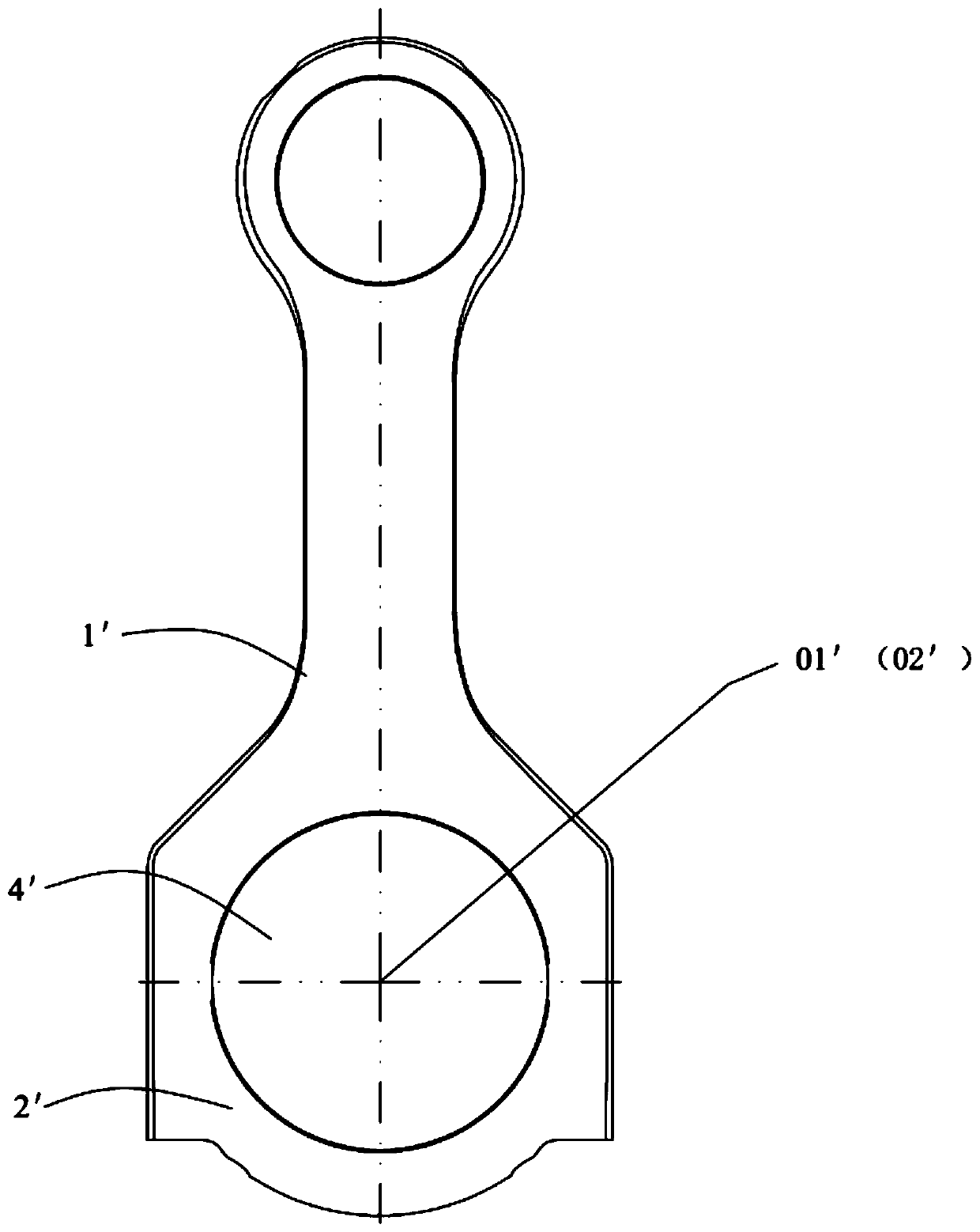
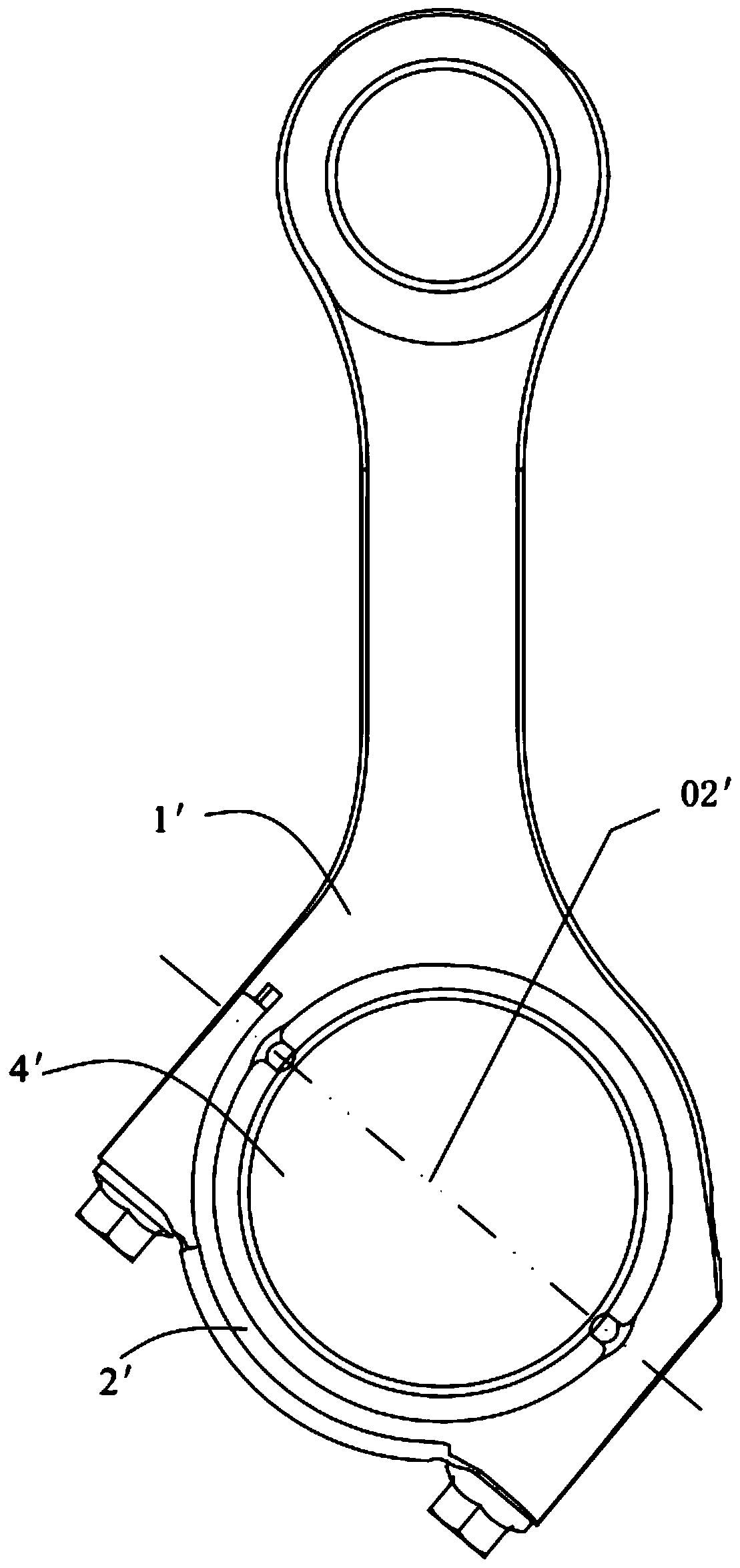
technical field [0001] The invention relates to the technical field of vehicles, in particular to a connecting rod structure and an engine. Background technique [0002] Existing connecting rod comprises connecting rod small end, connecting rod large end and connecting rod body, and connecting rod small end is the part that is connected with piston pin, and connecting rod large end is the part that is connected with crankshaft, and connecting rod body is connecting rod small end, connecting rod. The portion of the shaft between the large ends of the shaft. Since the connecting rod is respectively connected to the piston and the crankshaft, the connecting rod can bear the gas force from the piston pin and transmit it to the crankshaft to convert the reciprocating motion of the piston into the rotary motion of the crankshaft. [0003] The existing connecting rods are divided into flat cut connecting rods (such as figure 1 shown) and miter cut link (as figure 2 shown) two t...

Claims


Application Information

Patent Timeline
IPC IPC(8): F16C7/02
CPCF16C7/023
Inventor 王雪马燕燕唐建明崔凯周禹佳
Owner WEICHAI POWER CO LTD
Learn More