
Temperature-compensating and temperature-adjusting annealing furnace system

An annealing furnace and temperature adjustment technology, which is applied in furnaces, furnace types, heat treatment furnaces, etc., can solve the problems of low automation, sealing problems, and high manufacturing difficulty, and achieve high safety, good sealing, and reduce production costs. Effect

Active Publication Date: 2019-09-10
ZHEJIANG TIANQI CUP
View PDF7 Cites 0 Cited by
  • Summary
  • Abstract
  • Description
  • Claims
  • Application Information

AI Technical Summary

Problems solved by technology

Temperature-compensated crystal oscillators are widely used in various communication devices, such as smart phones, wireless walkie-talkies, wireless communication base stations, etc.; their production standards are high, their value is high, and their production is difficult, especially when vacuum annealing is the key during the production process. Existing The vacuum annealing furnace in the technology has problems in sealing, and the degree of automation is very low, but if the brake is added, such as the German Unitemp vacuum rapid annealing furnace, the French Annealsys high-temperature vacuum annealing furnace, etc., the price is too expensive, so it is necessary to A component that can add self-improvement on the existing basis, increase automation, but do not increase the cost of the enterprise

Method used


Image

  • Temperature-compensating and temperature-adjusting annealing furnace system
  • Temperature-compensating and temperature-adjusting annealing furnace system
  • Temperature-compensating and temperature-adjusting annealing furnace system

Examples


Embodiment 1

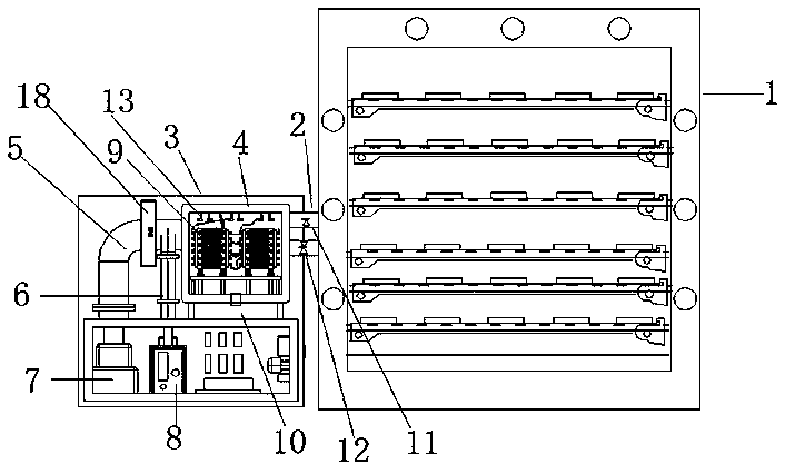
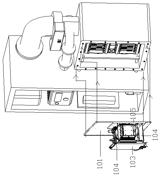
[0035] Embodiment 1: A temperature-supplementing and temperature-regulating annealing furnace system, including a furnace main body 1 and a complementary temperature regulator 3. The furnace main body 1 here mainly refers to a vacuum annealing furnace under the prior art, and what is required is that it is equipped with a prior art After the basic or integrated device is required, it is also necessary to set an interface of a compensation vent pipe 2 outward in its internal warehouse, and then set a compensation vent pipe 2 through this interface, and then the complementary thermostat 3 passes through the compensation The ventilation pipe 2 is connected with the furnace main body 1;

[0036] Wherein: the complementary thermostat 3 includes a thermostat chamber 4, a condensation vacuum tube 5, a mechanical vacuum tube 6, a condensation vacuum pump 7, a mechanical vacuum pump 8, 6 main components, and as figure 1 shown;

[0037] continue as figure 1 As shown, the temperature a...

Embodiment approach

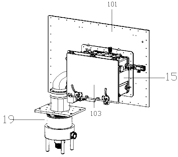
[0044] Implementation method: such as figure 1 As shown, after welding the additional warehouse cover plate 201, and assembling the main moving rail 202, the macro moving rail 215 is arranged between the outside of the cabin door 17 and the inside of the main moving rail 202, and then on the two sides The upper cover horizontal frame 203 is suspended horizontally between the two, and the cover horizontal frame 203 will combine the upper groove and protect the internal components, and the micro-motor carriage 210 at the bottom will correspond to the main moving rail 202 and the macro movement respectively. Rail 215, let the two move in linkage and move down to cover the hatch 17 for sealing. The correct moving distance of the sealing will be controlled by the grating sensor, and then the airtightness test after sealing will be carried out by itself. The airtightness sensor 1. The temperature sensor will monitor the data for feedback. If there is fluctuation or exceeds the stand...

Embodiment 2

[0054] Such as figure 1 As shown, a temperature-supplementing and temperature-regulating annealing furnace system includes a furnace body 1, a compensation vent pipe 2, and a complementary thermostat 3. The complementary thermostat 3 passes through the compensation vent pipe 2 and the furnace body 1, wherein: the Complementary thermostat 3 includes temperature regulation bin 4, condensation vacuum tube 5, mechanical vacuum tube 6, condensation vacuum pump 7, mechanical pumping vacuum pump 8, complementary thermostat 3 includes electric heating chip stack 9 set in temperature regulation bin 4 , the temperature sensor 13 is set in the temperature adjustment chamber 4, the compensation ventilation pipe 2 is connected to the condensation vacuum pump 7, the mechanical suction vacuum pipe 6 is connected to the mechanical suction vacuum pump 8, and the inlet of the mechanical suction vacuum pipe 6 is connected to the condensation suction vacuum pipe 5. The temperature chamber 4 is co...


PUM


Abstract

The invention relates to the field of electronic circuit crystal parts, in particular to a temperature-compensating and temperature-adjusting annealing furnace system. The temperature-supplementing and temperature-adjusting annealing furnace system comprises a furnace main body and a complementary temperature regulator, wherein the complementary temperature regulator is connected with the furnacemain body through a compensation vent pipe; the complementary temperature regulator comprises a temperature adjusting bin, a condensation vacuumizing pipe, a mechanical air exhaust vacuum pipe, a condensation vacuumizing pump and a mechanical air exhaust vacuum pump, wherein the temperature adjusting bin is connected with the furnace main body through the compensation vent pipe at the head end, anelectric heating sheet pile is arranged in the temperature adjusting bin, the tail end of the temperature adjusting bin communicates with the condensation vacuumizing pipe, the tail end of the condensation vacuumizing pipe is downwards connected with the condensation vacuumizing pump, and the mechanical air exhaust vacuum pipe is connected with the mechanical air exhaust vacuum pump; an inlet ofthe mechanical air exhaust vacuum pipe is connected with the condensation vacuumizing pipe, and a vacuumizing passage is formed by connecting the compensation vent pipe through the temperature adjusting bin to the condensation vacuumizing pipe and connected with the condensation vacuumizing pump; and a cooling bin is welded or hinged to the front bin wall of the temperature adjusting bin.

Description

technical field [0001] The invention relates to the field of electronic circuit crystal parts, in particular to a temperature-supplementing and temperature-regulating annealing furnace system. Background technique [0002] The temperature-compensated crystal oscillator is a kind of quartz crystal oscillator, which compensates the crystal oscillation frequency change caused by the ambient temperature change through the additional temperature compensation circuit in the internal temperature-compensated crystal oscillator chip, and realizes high-precision frequency temperature stability. Temperature-compensated crystal oscillators are widely used in various communication devices, such as smart phones, wireless walkie-talkies, wireless communication base stations, etc.; their production standards are high, their value is high, and their production is difficult, especially when vacuum annealing is the key during the production process. Existing The vacuum annealing furnace in the...

Claims


Application Information

Patent Timeline
Patent Type & Authority Applications(China)
IPC IPC(8): C21D9/00C21D1/74C21D11/00
CPCC21D9/00C21D1/74C21D11/00
Inventor 双著杰刘智武
Owner ZHEJIANG TIANQI CUP
Learn More