Multifunctional in-mold labeling mechanical arm and production line

An in-mold labeling and manipulator technology, applied in labeling machines, labels, packaging, etc., can solve the problems of complex overall structure, low production efficiency of the production line, shaking of label molds, etc., to achieve reduced connection components, high production efficiency, The effect of strong support

Pending Publication Date: 2019-09-10
GUANGDONG LONGXING PACKAGING IND
View PDF3 Cites 4 Cited by
  • Summary
  • Abstract
  • Description
  • Claims
  • Application Information

AI Technical Summary

Problems solved by technology

-Prone to crash due to the production line at the rear
At the same time, in this technical solution, the label mold, the sliding connecting seat and the horizontal sliding fastening seat are all located under the single-row multi-row support plate, and the horizontal sliding fastening seat hinders the backward movement of the label mold. It is possible to lengthen the single-row multi-row support plate forward, but due to the technical focus of multiple groups of mold mechanisms are concentrated on the rear, the length of the lengthened support plate is likely to cause the label mold to shake, which will cause the position of the mold to deviate. In the production process, from placing the label in the cup-making mold, the position accuracy of the suction and release label mold is extremely high. A slight deviation will prevent the mold from entering the cup-making mold smoothly, so that the in-mold labeling cannot be carried out smoothly.
Moreover, the disclosed prior multi-arrangement automatic telescopic in-mold labeling manipulator uses multiple sliding connection seats, the overall structure is complex and heavy, which is not conducive to the overall high-speed operation of the manipulator.
At the same time, the production efficiency of the existing in-mold labeling production line is not high

Method used


Image

  • Multifunctional in-mold labeling mechanical arm and production line
  • Multifunctional in-mold labeling mechanical arm and production line
  • Multifunctional in-mold labeling mechanical arm and production line

Examples


Embodiment 1

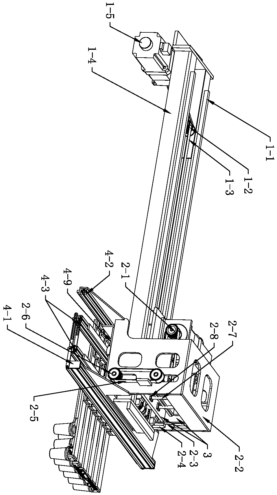
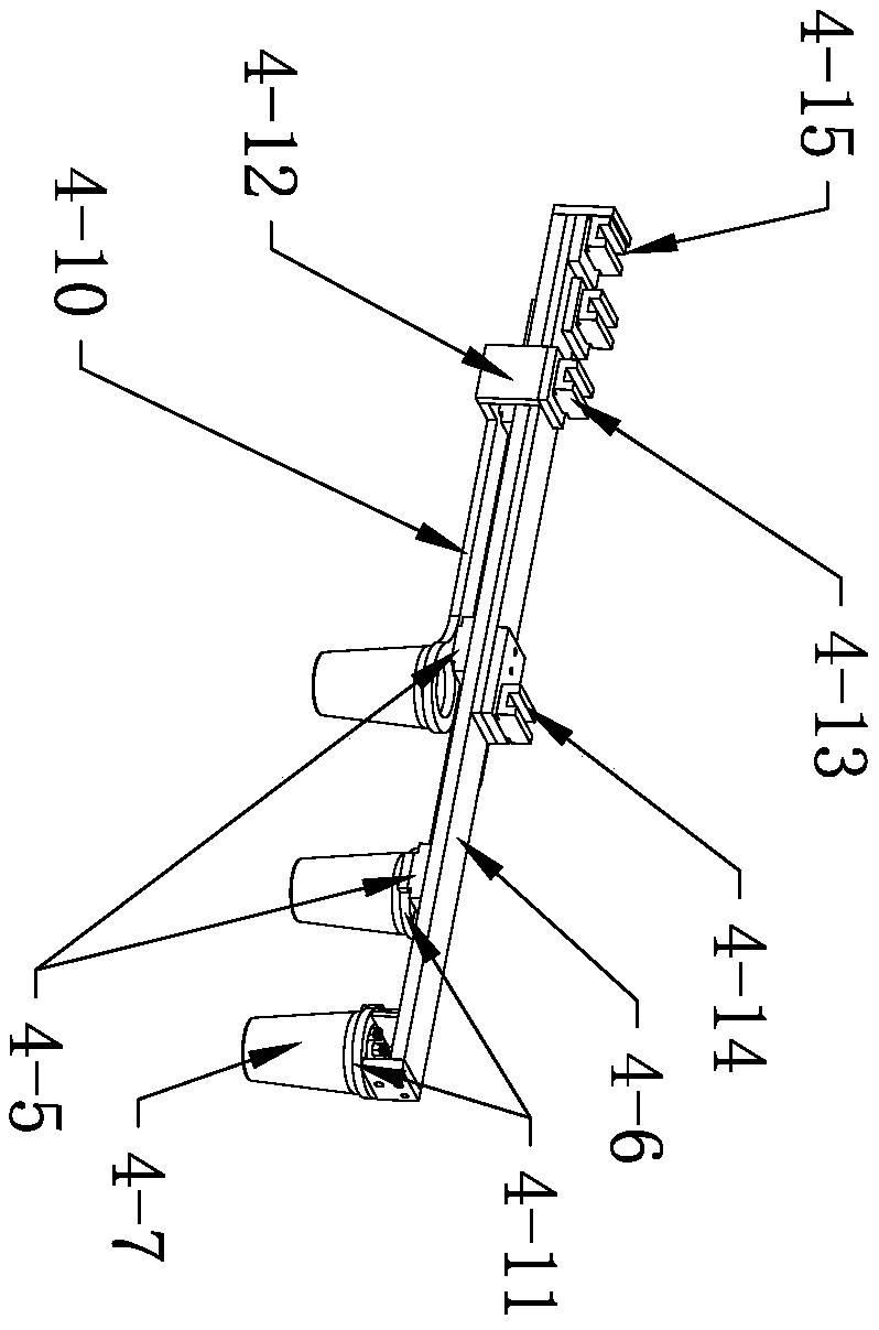
[0076] see Figure 1 to Figure 11The multifunctional in-mold labeling manipulator of this embodiment includes a translation mechanism, a lifting mechanism 2, a translation lifting support seat 3 and a label removal mechanism 4. Under the action of the translation mechanism and the lifting mechanism 2, the label removal mechanism 4 can be Translation and lifting movement. In this embodiment, the translation mechanism includes a translation support frame 1-4, a translation drive motor 1-5, a translation synchronous belt 1-3 and a translation synchronous wheel 1-2, and the two ends of the translation support frame 1-4 are respectively installed with translation synchronous Wheel 1-2, the translation synchronous wheel 1-2 is driven by the translation drive motor 1-5, the translation synchronous belt 1-3 is installed on the synchronous wheel, and translation guide rails 1-1 are respectively installed on both sides of the translation support frame 1-4, The translational lifting sup...


PUM


Abstract

The invention relates to a multifunctional in-mold labeling mechanical arm and a production line. The multifunctional in-mold labeling mechanical arm comprises a translation mechanism, a lifting mechanism, a translation lifting support seat and a label loading and unloading mechanism. Under the action of the translation mechanism and the lifting mechanism, the label loading and unloading mechanismcan do translation and lifting movement; and a plurality of telescopic convex molds of the label loading and unloading mechanism can extend out or shrink back in the longitudinal and transverse directions. Compared with the prior art, (1) swing of label molds cannot be caused by length increase caused by increasing the label mold row number; (2) the multifunctional in-mold labeling mechanical armruns more smoothly and has higher production efficiency; (3) the weight is small, and high-speed running of the mechanical arm is facilitated; and (4) the support strength is effectively increased, deformation is avoided, and the accuracy of the positional movement of the label molds is ensured. The production line can realize integration of cup making and cup labeling in the molds, complete automation is achieved, high-speed operation of the equipment is achieved, the structure is compact and simple, the equipment operation steps are fewer, and the production efficiency is high.

Description

technical field [0001] The invention relates to the technical field of disposable cup preparation, in particular to a multifunctional in-mold labeling manipulator and a production line. Background technique [0002] The plastic cup making machine is used to form PP, PS, HIPS, PVC, PET, PLA and other plastic sheets into various cups, bowls, plates, covers, boxes and other products such as milk cups, biscuit cups, food cups, Butter cups, instant noodle bowls, etc. In-mold labeling technology is to put the printed and hot-pressed film label into the mold, put plastic parts, such as white cups, lids or other materials, and then use the high temperature and high pressure in the mold to combine the film label with the blown label. The surface of the outer wall of the plastic part or injection molded part is fused together, so that the film label and the blow molded part or injection molded part can be hot melt pasted at one time. Compared with the pressure-air thermoforming cont...

Claims


Application Information

Patent Timeline
IPC IPC(8): B65C9/02B65C9/08
CPCB65C9/02B65C9/08
Inventor 王昌佑王贤淮
Owner GUANGDONG LONGXING PACKAGING IND
Why Eureka
Try Eureka