
Hybrid rotor continuous pole permanent magnet synchronous motor and method for reducing torque ripple thereof

A permanent magnet synchronous motor, torque pulsation technology, applied in electric components, magnetic circuit rotating parts, magnetic circuit and other directions, can solve the problems of permanent magnets prone to demagnetization, large permanent magnet eddy current loss, etc., and achieve high permanent magnet utilization. efficiency, high torque density, high efficiency

Active Publication Date: 2019-09-06
JIANGSU UNIV
View PDF11 Cites 6 Cited by
  • Summary
  • Abstract
  • Description
  • Claims
  • Application Information

AI Technical Summary

Problems solved by technology

The eddy current loss of the permanent magnet of the traditional continuous pole permanent magnet synchronous motor is large, and the permanent magnet is prone to demagnetization when overloaded. Therefore, it is very meaningful and necessary to reduce the eddy current loss of the permanent magnet and enhance the anti-demagnetization ability of the permanent magnet to improve the efficiency and reliability of the motor.

Method used


Image

  • Hybrid rotor continuous pole permanent magnet synchronous motor and method for reducing torque ripple thereof
  • Hybrid rotor continuous pole permanent magnet synchronous motor and method for reducing torque ripple thereof
  • Hybrid rotor continuous pole permanent magnet synchronous motor and method for reducing torque ripple thereof

Examples


Embodiment Construction

[0039] The following will clearly and completely describe the technical solutions in the embodiments of the present invention with reference to the drawings in the embodiments of the present invention.

[0040] The embodiments described below by referring to the figures are exemplary only for explaining the present invention and should not be construed as limiting the present invention.

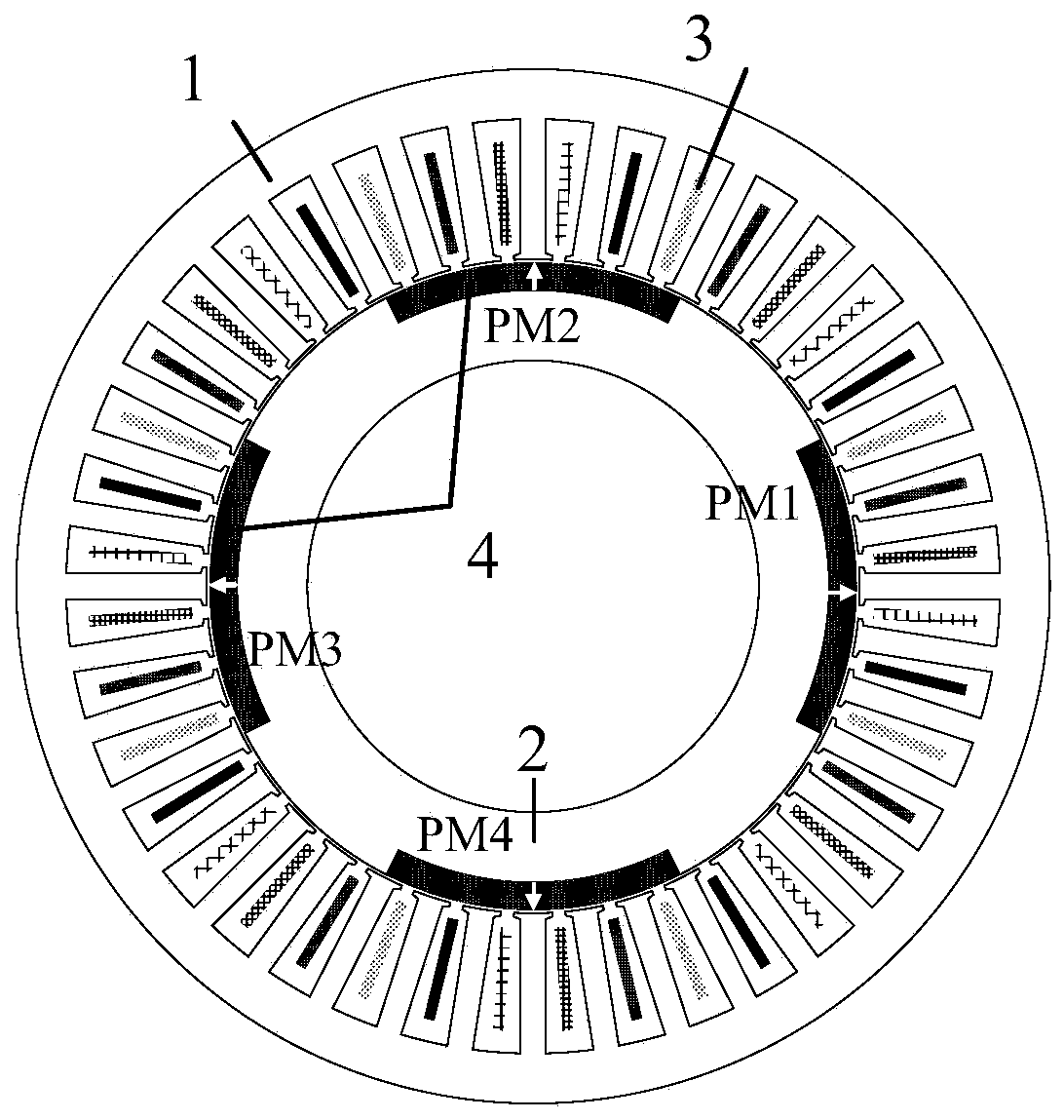
[0041] figure 1 It is a structural schematic diagram of a traditional continuous pole permanent magnet synchronous motor (original motor) in the present invention. Such as figure 1 As shown, the traditional continuous pole permanent magnet synchronous motor includes an outer stator 1 and an inner rotor 2; the outer stator 1 includes 40 stator slots and armature windings 3 embedded therein; the inner rotor 2 includes a rotor core, 4 An arc-shaped permanent magnet pole 4.

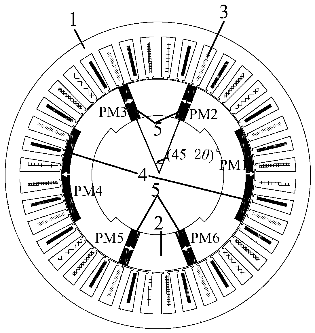
[0042] figure 2 It is a structural schematic diagram of a hybrid rotor continuous pole permanent magnet synchronous m...


PUM


Abstract

The invention discloses a hybrid rotor continuous pole permanent magnet synchronous motor and a method for reducing torque ripple thereof. The hybrid rotor continuous pole permanent magnet synchronousmotor comprises an outer stator and an inner rotor. The outer stator is provided with five phases of distributed armature windings; and the inner rotor is provided with surface-embedded permanent magnets and spoke type permanent magnets. The method for reducing torque ripple of the hybrid rotor continuous pole permanent magnet synchronous motor comprises the following specific steps: to begin with, increasing phase number of the permanent magnet motors to reduce the torque ripples; then, optimizing pole arc coefficient and thickness of the surface-embedded permanent magnets and the length andwidth of the spoke type permanent magnets to reduce the torque ripples again; and carrying out angular deflection on the spoke type permanent magnets to further reduce the torque ripples. The motor overcomes the disadvantages of large torque ripple, large eddy-current loss of the permanent magnets and easy demagnetization of the permanent magnets when overloaded of a conventional continuous polepermanent magnet synchronous motor, and meanwhile, maintains the characteristics of high torque density and high utilization rate of the permanent magnets of an original motor.

Description

technical field [0001] The invention relates to the design of a hybrid rotor continuous pole permanent magnet synchronous motor, in particular to a method for reducing torque ripple of a hybrid rotor continuous pole permanent magnet synchronous motor, belonging to the technical field of motor manufacturing. Background technique [0002] Nowadays, permanent magnet synchronous motors have been widely used, and they play a very important role in many fields from automobiles to aerospace. This is mainly due to several salient features of permanent magnet synchronous motors, including high torque density, high efficiency, and small weight and volume. The permanent magnet synchronous motor uses a magnetic material with a high magnetic energy product to replace the traditional excitation winding, which not only eliminates the negative impact of the excitation winding, but also simplifies the mechanical structure of the motor, which improves the reliability of the motor and reduces ...

Claims


Application Information

Patent Timeline
Patent Type & Authority Applications(China)
IPC IPC(8): H02K1/27H02K29/03
CPCH02K1/276H02K1/278H02K29/03H02K2213/03
Inventor 翟芳芳刘国海陈前徐高红
Owner JIANGSU UNIV
Learn More