
Light-touch power-assisted switch ultrathin pilot valve element

A pilot valve core and valve core technology, which is applied in the field of ultra-thin pilot valve cores of light touch power switches, can solve the problems of non-opening, small flow, and blockage of diaphragm damping holes, so as to achieve comfortable pressing feeling and ultra-light pressing force. , the effect of increasing the aesthetics

Pending Publication Date: 2019-09-06
李巍
View PDF0 Cites 0 Cited by
  • Summary
  • Abstract
  • Description
  • Claims
  • Application Information

AI Technical Summary

Problems solved by technology

However, the existing pilot valve push switch in the industry is very unstable when the water pressure is low, there are low-pressure water leakage or no water shut-off, low-pressure opening difficulty, low flow rate or no opening, etc., and the water pressure acts when the water pressure is low The thrust on the diaphragm is very small, the opening of the diaphragm will be in a tilted critical vibration state, and the effluent flow will have pulse changes; on the other hand, when used in an environment with dirty water, the diaphragm damping hole is easy to be blocked, resulting in malfunction. The situation of failure occurs, and the length of the existing pilot spool on the market is relatively long, so that the product design must be designed as a storage case to install the button spool, which brings great limitations to product design and increases the production cost of the product

Method used


Image

  • Light-touch power-assisted switch ultrathin pilot valve element
  • Light-touch power-assisted switch ultrathin pilot valve element
  • Light-touch power-assisted switch ultrathin pilot valve element

Examples


Embodiment Construction

[0031] The following will clearly and completely describe the technical solutions in the embodiments of the present invention with reference to the accompanying drawings in the embodiments of the present invention. Obviously, the described embodiments are only some of the embodiments of the present invention, not all of them. Based on the embodiments of the present invention, all other embodiments obtained by persons of ordinary skill in the art without creative work, any modifications, equivalent replacements, improvements, etc., shall be included in the protection scope of the present invention Inside.

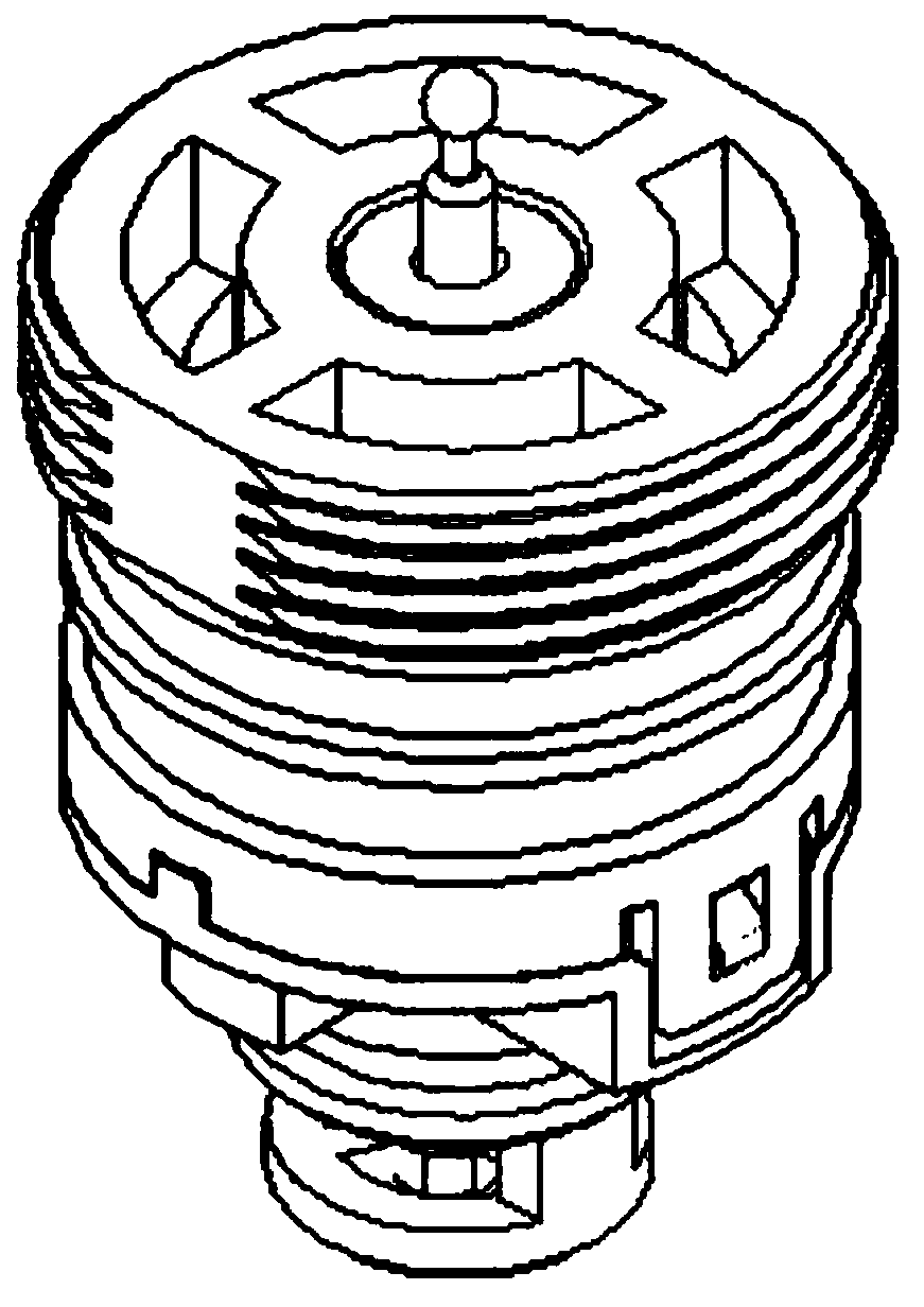
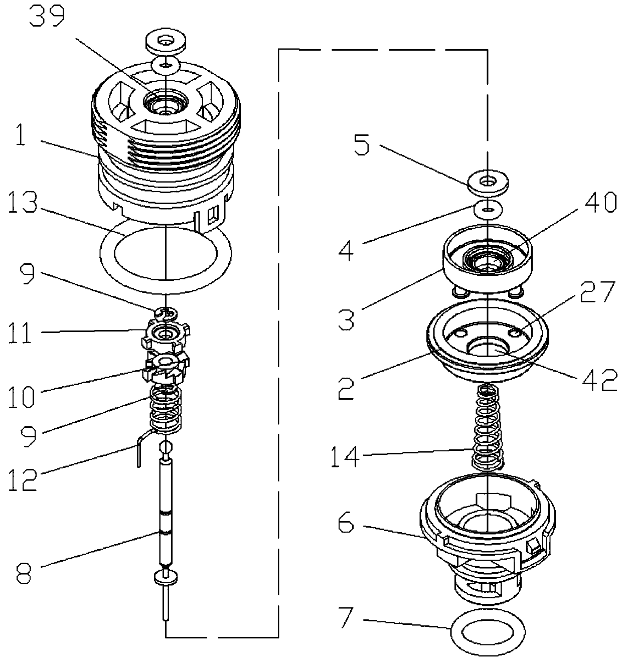
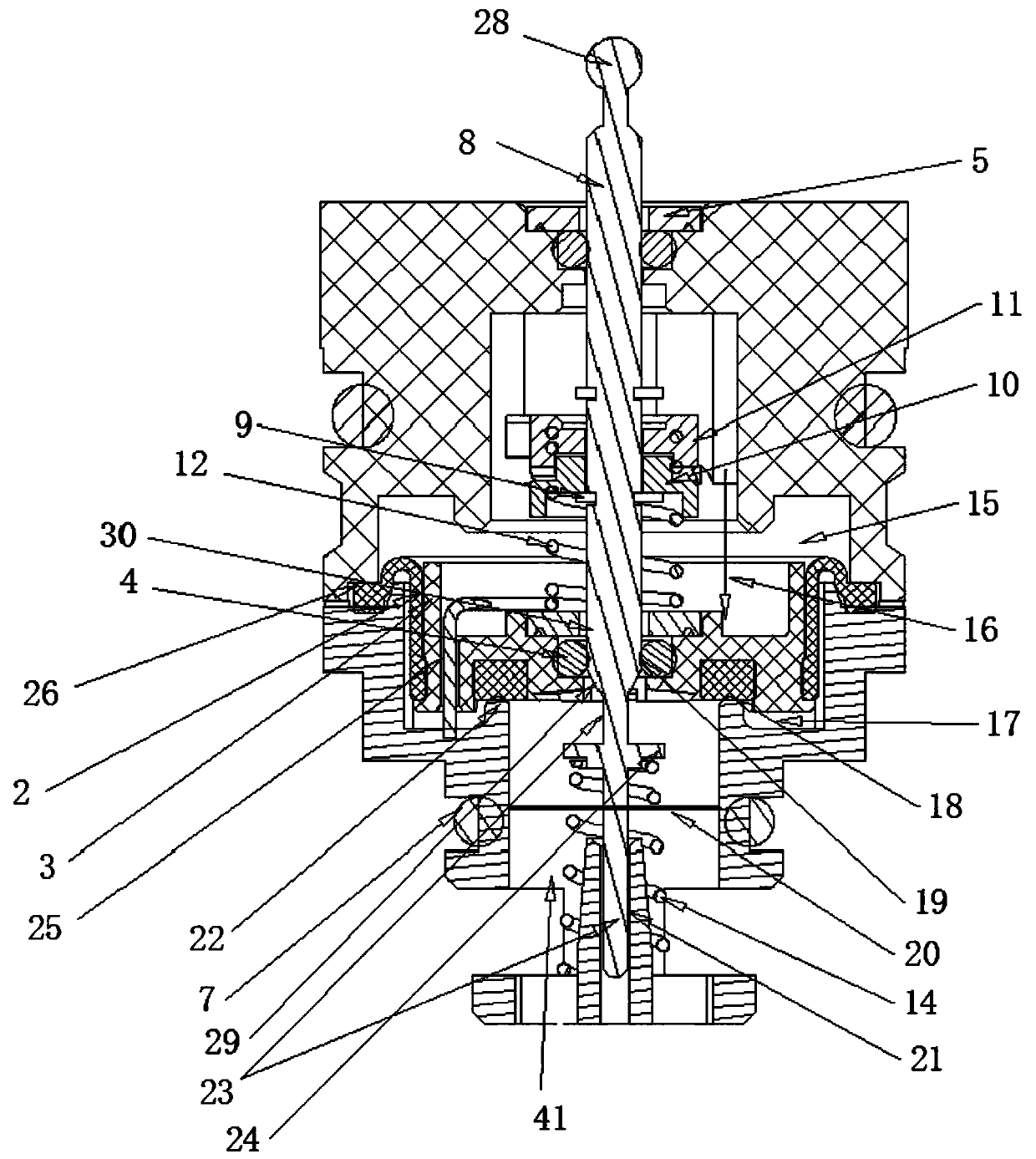
[0032] Such as Figure 1 to Figure 9 As shown, an ultra-thin pilot spool of a soft touch power switch includes a spool base 6 and a spool shell 1, and the buckle on the outside of the spool shell 1 is connected with the buckle position 38 on the spool base 6. Diaphragm 2 is sleeved in the spool base 6, and the edge of the diaphragm 2 is arranged at the joint between the upp...


PUM


Abstract

The invention discloses a light-touch power-assisted switch ultrathin pilot valve element. The light-touch power-assisted switch ultrathin pilot valve element comprises a valve element base. The valveelement base is connected with a valve element shell in a clamped manner. A diaphragm is connected inside the valve element base in a sleeving manner. A damping piece is arranged inside the diaphragm. A switch shaft is connected inside the damping piece in a sleeving manner. The switch shaft comprises a shaft straight segment, a shaft diameter oblique segment and a shaft diameter segment. A shaftshoulder segment is arranged on the shaft diameter segment. An opening spring is connected to the outer side of the shaft diameter segment in a sleeving manner. A boss is arranged in the inner side face of the valve element base below the diaphragm. Water input through holes are formed in the portion, on the outer side of the boss, of the valve element base. Water output through holes are formedat the bottom end of the valve element base. A driving pushing part, a driven pushing part and C-shaped clamping rings are connected to the outer side of the shaft straight segment in a sleeving manner. Tooth-hanging positions are arranged in the outer side of the driven pushing part. The driven pushing part is connected with an opening tooth position or a closing tooth position in the inner sideof the valve element shell in a clamped manner through the tooth-hanging positions. A closing spring is connected to the outer side of the shaft straight segment below the driven pushing part in a sleeving manner. After penetrating through the top end of the valve element shell, the top end of the shaft straight segment is arranged on the outer side of the valve element shell.

Description

technical field [0001] The invention relates to the field of switches, in particular to an ultra-thin pilot valve core of a light touch power-assisted switch. Background technique [0002] At present, the push switch spool in the industry adopts the principle of pilot valve, and uses the small-area auxiliary waterway switch to control the main control valve and the large-area piston or diaphragm to switch the main waterway, so that the waterway switch can be controlled with very light force, and press Hand feel is not affected by changes in water pressure. However, the existing pilot valve push switch in the industry is very unstable when the water pressure is low, there are low-pressure water leakage or no water shut-off, low-pressure opening difficulty, low flow rate or no opening, etc., and the water pressure acts when the water pressure is low The thrust on the diaphragm is very small, the opening of the diaphragm will be in a tilted critical vibration state, and the ef...

Claims


Application Information

Patent Timeline
IPC IPC(8): F16K39/02F16K31/44F16K1/00
CPCF16K1/00F16K31/44F16K39/024
Inventor 李巍
Owner 李巍
Learn More