
Cold, heat and electricity combined storage and combined supply system

A technology of cooling, heating, power, and co-supply, which is applied to steam engine devices, machines/engines, mechanical equipment, etc., can solve problems such as rising prices, low energy density of compressed air energy storage systems, and low energy storage density of compressed air energy storage technology , to achieve high efficiency, high energy storage density and low cost

Active Publication Date: 2019-09-06
INST OF ENGINEERING THERMOPHYSICS - CHINESE ACAD OF SCI
View PDF11 Cites 28 Cited by
  • Summary
  • Abstract
  • Description
  • Claims
  • Application Information

AI Technical Summary

Problems solved by technology

However, the energy storage density of compressed air energy storage technology is low, and the difficulty lies in the need for suitable places where compressed air can be stored, such as sealed caves or abandoned mines, etc.
Moreover, the compressed air energy storage system still relies on the burning of fossil fuels to provide heat sources. On the one hand, it faces the threat of the gradual depletion of fossil fuels and rising prices; Zero emissions), renewable energy development requirements
[0006] In order to solve the main problems faced by traditional compressed air energy storage systems, domestic and foreign scholars have carried out advanced adiabatic compressed air energy storage systems (AACAES), surface compressed air energy storage systems (SVCAES), compressed air storage Energy storage system (AACAES) and air-steam combined cycle compressed air energy storage system (CASH), etc., make the compressed air energy storage system basically avoid burning fossil fuels, but the energy density of the compressed air energy storage system is still very low, requiring a large storage chamber

Method used


Image

  • Cold, heat and electricity combined storage and combined supply system

Examples


Embodiment Construction

[0028] In order to make the object, technical solution and advantages of the present invention clearer, the present invention will be further described in detail below with reference to the accompanying drawings and examples.

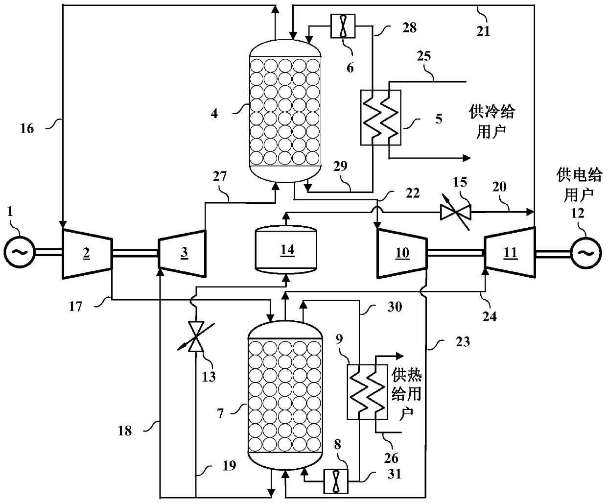
[0029] Such as figure 1 As shown, the system based on combined cooling, heating, power storage and joint supply of the present invention is mainly composed of a drive unit 1, an energy storage compressor unit 2, an energy storage expansion unit 3, a regenerator 4, a low-temperature heat exchanger 5, a heat accumulator 7, and a cryogenic pump 6. High temperature pump 8, high temperature heat exchanger 9, energy release compressor unit 10, energy release expansion unit 11, power generation unit 12, buffer tank 14, valves 13, 15 and multiple pipelines 16-27 and other components.

[0030] The above-mentioned system of the present invention can be divided into a heat pump heating and refrigeration circuit as a whole, a cold and heat energy heat engine power ...


PUM


Abstract

The invention discloses a cold, heat and electricity combined storage and combined supply system. The system comprises a heat pump heating and cooling energy storage loop, a cold and heat energy heatengine power generation loop, a heat supply loop and a cold supply loop; power station off-peak (cheap) electricity is used for driving a heat pump heating and cooling circular loop to make high-temperature heat energy and low-temperature cold energy, the heat energy and the cold energy are stored in a heat storage device and a cold storage device, at the power utilization moment, gas in the loopsabsorbs the stored high-temperature heat energy and the stored low-temperature cold energy, through heat engine circulation, an electric generator is driven to generate electricity, and the electricity is supplied to a user. On the heat using time interval, the heat supply loop supplies the heat energy in the heat storage device to the user through the heat exchanger, and on the cold using time interval, the cold supply loop supplies the heat energy in the cold storage device to the user through the heat exchanger. Through the cold, heat and electricity combined storage and combined supply system, simultaneous storage and supply of cold, heat and electricity can be achieved, various needs of the user can be met, and the system has the advantages of being high in energy storage density, low in cost, high in efficiency, suitable for power grid peak shaving and various renewable power stations, free of generating room temperature gas and the like.

Description

technical field [0001] The invention belongs to the technical field of energy storage, and relates to a cooling, heating, power storage and joint supply system. and thermal energy supply to the user's system. Background technique [0002] Traditional distributed energy supply combined cooling, heating and electricity systems generally include power generation, waste heat heating, waste heat refrigeration and other links. At present, a lot of research has been done on the combined cooling, heating, power and power generation system including cold storage and heat storage, but there are relatively few studies considering the power storage system, especially the research on the mutual conversion and joint supply of cooling, heating and power storage has not been reported yet. [0003] At present, the existing power energy storage technologies include pumped water energy storage, compressed air energy storage, battery energy storage, superconducting magnetic energy, flywheel en...

Claims


Application Information

Patent Timeline
IPC IPC(8): F01K7/02F01K13/02F01K25/08F01K21/00
CPCF01K7/02F01K13/02F01K25/08F01K21/00
Inventor 王亮陈海生张涵谢宁宁彭珑
Owner INST OF ENGINEERING THERMOPHYSICS - CHINESE ACAD OF SCI
Learn More