Steel formwork and manufacturing method thereof

A technology of steel formwork and supporting formwork, which is applied in the field of steel formwork and its production, can solve the problems of low construction efficiency, low degree of mechanization, and large labor demand, and achieve the effects of avoiding complex construction, strong applicability, and reducing self-weight

Inactive Publication Date: 2019-09-06
SCEGC NO 5 CONSTRUCTION ENGINEERING GROUP COMPANYLTD
View PDF7 Cites 1 Cited by
  • Summary
  • Abstract
  • Description
  • Claims
  • Application Information

AI Technical Summary

Problems solved by technology

Traditional cast-in-place column construction requires erection of operational scaffolding, steel bar binding, formwork support, etc. to be completed at the construction site. The construction efficiency is low, the degree of mechanization is low, and the demand for labor is large. At the same time, it affects the development of PC and steel structure processes. On the basis of construction period and molding quality, optimize the construction drawings and construction technology of cast-in-place concrete columns, improve labor tools, change labor methods, and use mechanization to cooperate with construction to meet the requirements of free scaffolding for construction operations. It is urgent to design steel formwork to realize column reinforcement cages. Assembled with the steel formwork on the ground, the construction process is simplified, and the factory-like and standardized construction of the concrete cast-in-place columns at the logistics storage construction site improves the construction speed and construction quality while ensuring green construction and construction safety

Method used


Image

  • Steel formwork and manufacturing method thereof
  • Steel formwork and manufacturing method thereof
  • Steel formwork and manufacturing method thereof

Examples


Embodiment Construction

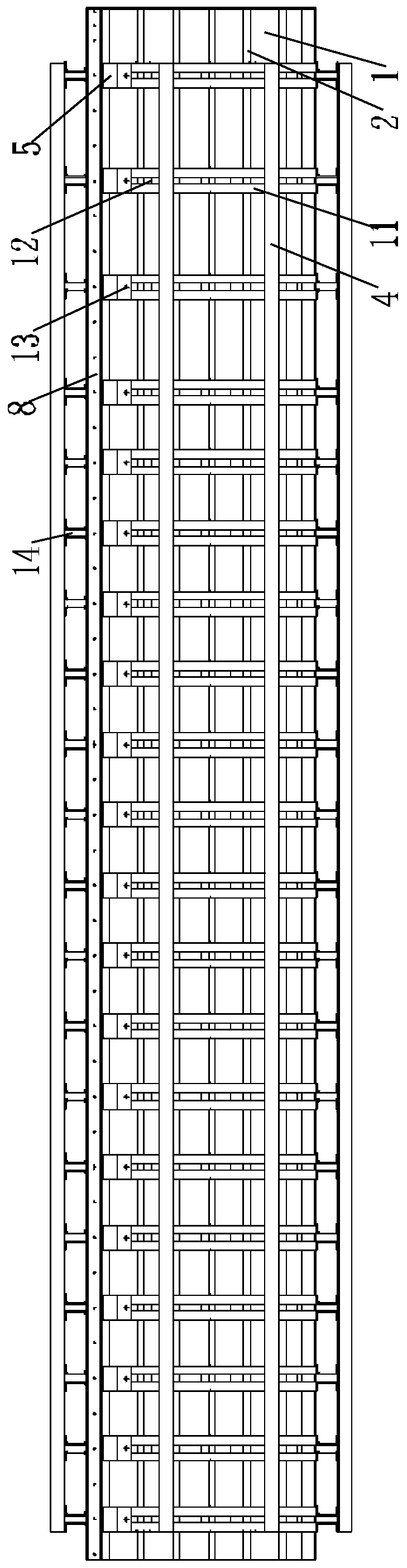
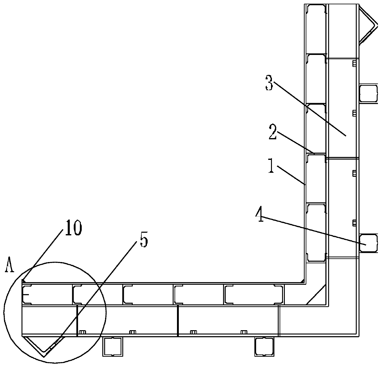
[0048] Such as Figure 1 to Figure 4 As shown, a steel formwork according to the present invention includes a first L-shaped steel support formwork and a second L-shaped steel support formwork matched with the first L-shaped steel support formwork, and the first L-shaped steel support formwork The structural dimensions of the formwork and the second L-shaped steel formwork are the same, and the first L-shaped steel formwork includes an L-shaped steel panel 1, a secondary reinforcement layer fixed on the outer surface of the L-shaped steel panel 1, fixed on the The main reinforcement layer on the outside of the secondary reinforcement layer and the reinforcement layer fixed on the outside of the main reinforcement layer, the secondary reinforcement layer includes a plurality of secondary reinforcements 2 fixed on the outer surface of the L-shaped steel panel 1 in parallel and arranged vertically, The main rib layer includes a plurality of L-shaped main ribs 3 arranged along the...


PUM


Abstract

The invention discloses a steel formwork and a manufacturing method thereof. The steel formwork comprises first L-shaped steel supporting formworks and second L-shaped steel supporting formworks whichare the same in structure and size, and each first L-shaped steel supporting formwork sequentially comprises an L-shaped steel face plate, a secondary rib layer, a primary rib layer and a reinforcinglayer from inside to outside. The manufacturing method comprises the steps that first, the specifications of the steel formwork are planned; second, the total load borne by the steel formwork is obtained; third, the design deformation amount of the steel formwork is calculated; fourth, a finite element model of the steel formwork is established, and the strength and the deflection of the steel formwork are verified; and fifth, the steel formwork is manufactured. The steel formwork with the four sealed walls is formed by the first L-shaped steel supporting formworks and the second L-shaped steel supporting formworks in an assembled mode, the steel formwork is fastened to the connection positions of the first L-shaped steel supporting formworks and the second L-shaped steel supporting formworks through a plurality of tie bars, through design of double L-shaped transverse pressure-bearing plates, the self weight of the steel formwork is decreased while the lateral pressure is ensured, and a gap between the L-shaped transverse pressure-bearing plates allows the tie bars to be inserted.

Description

technical field [0001] The invention belongs to the technical field of steel formwork, and in particular relates to a steel formwork and a manufacturing method thereof. Background technique [0002] With the development of my country's economy, there are more and more large-scale industrial plants and logistics warehouses in engineering construction, and more steel structures, PC, and cast-in-place concrete composite structures are used. The cast-in-place concrete columns are used as the main load-bearing columns, and the speed of on-site fabrication becomes a constraint The key to the installation of PC components and roof trusses. The traditional construction techniques of scaffolding, formwork and concrete pouring are no longer suitable for the construction of large industrial plants and logistics warehouses. Traditional cast-in-place column construction requires erection of operational scaffolding, steel bar binding, formwork support, etc. to be completed at the construc...

Claims


Application Information

Patent Timeline
Patent Type & Authority Applications(China)
IPC IPC(8): E04G9/06E04G13/02
CPCE04G9/06E04G13/02
Inventor 屈磊张雪峰昝俊锋贠子斌吴东刘一智梁毅庄稼宋小钢贺鹏鹏
Owner SCEGC NO 5 CONSTRUCTION ENGINEERING GROUP COMPANYLTD
Why Eureka
Try Eureka