Driving mechanism of longitudinal lateral moving type movable bridge

A driving mechanism and translational technology, which is applied in bridges, pedestrian bridges, bridge forms, etc., can solve problems such as inability to adapt to floating deformation and safety requirements, poor deformation of mobile bridges and main structures, and large spans of longitudinal translational open bridges. Achieve the effects of enhanced anti-overturning ability, good stability, and good deformation adaptability

Pending Publication Date: 2019-09-06
SHANGHAI MUNICIPAL ENG DESIGN INST GRP +1
View PDF0 Cites 0 Cited by
  • Summary
  • Abstract
  • Description
  • Claims
  • Application Information

AI Technical Summary

Problems solved by technology

However, due to the large span and complex structure of the longitudinal translation open bridge, in addition to the high requirements for the synchronization of the movement of each structure in the open state, the upper structure will produce downward deflection during the process of driving and the longitudinal movement of the lower mobile bridge, resulting in the movement of the bridge. There is a difference in deformation between the main structures, and from the perspective of safety, in the event of a power failure of the drive motor, the drive motor is required to have a self-locking function to prevent the mobile bridge from sliding down, and the traditional drive mechanism cannot meet the above floating deformation and safety requirements , it is urgent to develop a new driving mechanism

Method used


Image

  • Driving mechanism of longitudinal lateral moving type movable bridge
  • Driving mechanism of longitudinal lateral moving type movable bridge
  • Driving mechanism of longitudinal lateral moving type movable bridge

Examples


Embodiment

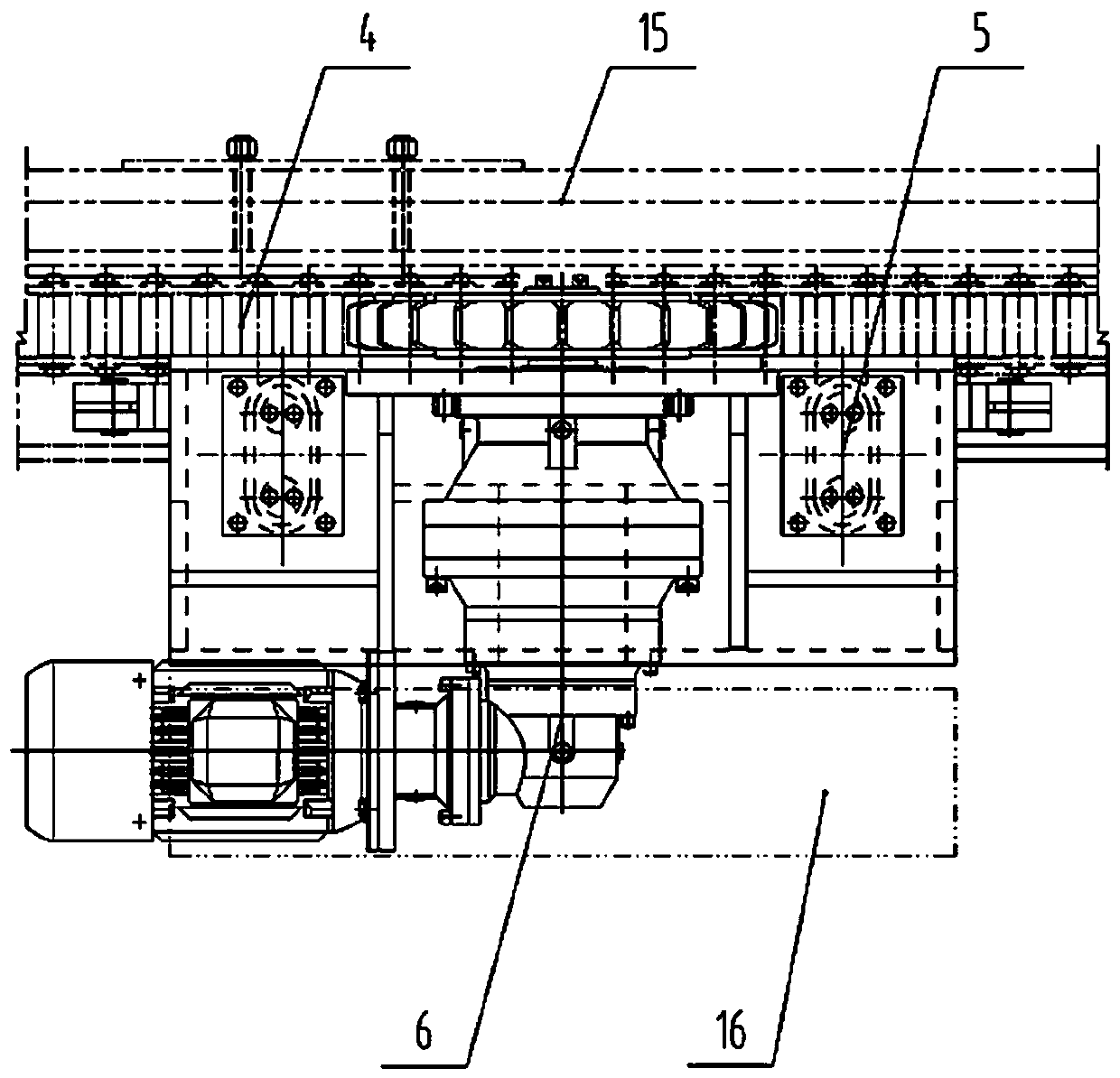
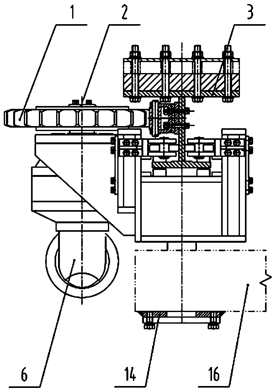
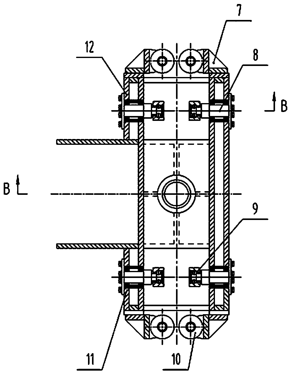
[0033] A drive mechanism for a longitudinal translation open bridge, such as Figure 1-Figure 4As shown, the drive mechanism includes a drive track 3, a chain drive, a fixed bridge 15, a movable bridge 16 and a drive slider frame 12, the drive track is fixed on the fixed bridge 15, and the chain drive includes a belt There is a geared motor 6 and a chain track 4 with an output shaft, the output shaft of the geared motor is provided with a sprocket 1 with gear teeth, and the sprocket 1 meshes with the chain track 4 to drive the drive slider frame 12 walk along the drive track 3, the chain track 4 is fixed on the drive track 3, the reduction motor 6 is fixed on the drive slider frame 12, and the upper end of the drive slider frame 12 passes through the horizontal and the vertical guide mechanism are suspended on the driving track 3, the lower end of the driving slider frame 12 is connected with the moving bridge 16 through a vertical large pin 13, and the lower end of the vertic...


PUM


Abstract

The invention discloses a driving mechanism for a longitudinal lateral moving type movable bridge. The driving mechanism comprises a driving rail, a chain driving device, a fixed bridge frame, a moving bridge frame and a driving sliding block frame; the driving rail is fixed to the fixed bridge frame; the chain driving device comprises a geared motor with an output shaft and a chain track, the output shaft of the geared motor is provided with a sprocket wheel, the sprocket wheel meshes with the chain track, the geared motor is fixed to the driving sliding block frame, and the chain track is fixed to the fixed bridge frame; the upper end of the driving sliding block frame is suspended on the driving track through a horizontal guiding mechanism and a vertical guiding direction, and the lowerend of the driving sliding block frame is connected with the moving bridge frame through a vertical large hinge pin; and the driving mechanism comprises a synchronous driving controller, the synchronous driving controller is electrically connected with the geared motor. The driving mechanism drives the driving sliding block frame and the moving bridge frame to perform longitudinal lateral movingalong the driving track through the meshing action of the sprocket wheel and the chain track, thereby realizing the telescopic opening of a lower layer deck; and the operation is stable and reliable,the adaptability to the bridge deformation is high, and the control precision is high.

Description

technical field [0001] The invention relates to a drive mechanism, in particular to a drive mechanism for providing power in a longitudinal translation type open bridge, and belongs to the technical field of open bridge drive mechanisms. Background technique [0002] The open bridge is also known as the movable bridge and the open and close bridge. The open bridge can improve the clearance height of the bridge and make it possible to build bridges on some rivers where bridges cannot be built. . The advantage is that the piers are relatively low, which can greatly reduce the conditions for connecting slopes on both banks, reduce the engineering volume of approach bridges and embankments on both banks, and make it possible for non-motorized vehicles to cross the river with limited longitudinal slopes. At present, the existing opening bridges at home and abroad mainly include three types: horizontal rotation type, vertical rotation type, and vertical lifting type. The span st...

Claims


Application Information

Patent Timeline
Patent Type & Authority Applications(China)
IPC IPC(8): E01D15/10
CPCE01D15/10
Inventor 马骉顾民杰卞永明刘广军王青桥
Owner SHANGHAI MUNICIPAL ENG DESIGN INST GRP
Why Eureka
Try Eureka