
Printing ink defoaming equipment utilizing airflow positive pressure vibration

A printing ink and defoaming technology, applied in printing, printing machine, degassing by vibrating liquid, etc., can solve the problems of limited vibration range, difficult defoaming, affecting printing quality, etc., to achieve the effect of eliminating air bubbles

Active Publication Date: 2019-09-06
东莞市南粤印刷有限公司
View PDF6 Cites 4 Cited by
  • Summary
  • Abstract
  • Description
  • Claims
  • Application Information

AI Technical Summary

Problems solved by technology

[0003] With the development of science and technology, the preparation of ink is becoming more and more precise, but in the process of ink filling, due to the high viscosity of ink and the high surface tension of ink, it is difficult for the gas in the ink to escape from the ink film and stay in the ink layer. In this way, air bubbles are generated in the ink. For the elimination of air bubbles, in the prior art, a vibrating device is often installed on the inner bottom of the ink tank. The vibrating device vibrates, and the air bubbles in the liquid ink can be vibrated up and eliminated, but the ink tank is The groove-shaped structure is designed, so the range of vibration is limited, and it is difficult to achieve the effect of defoaming. In addition, if the ink is still for a long time, it will produce flocculent substances at the bottom, which will affect the printing quality. Therefore, a positive airflow vibration Printing ink defoaming equipment

Method used


Image

  • Printing ink defoaming equipment utilizing airflow positive pressure vibration
  • Printing ink defoaming equipment utilizing airflow positive pressure vibration
  • Printing ink defoaming equipment utilizing airflow positive pressure vibration

Examples


Embodiment Construction

[0020] The following will clearly and completely describe the technical solutions in the embodiments of the present invention with reference to the accompanying drawings in the embodiments of the present invention. Obviously, the described embodiments are only some, not all, embodiments of the present invention. Based on the embodiments of the present invention, all other embodiments obtained by persons of ordinary skill in the art without making creative efforts belong to the protection scope of the present invention.

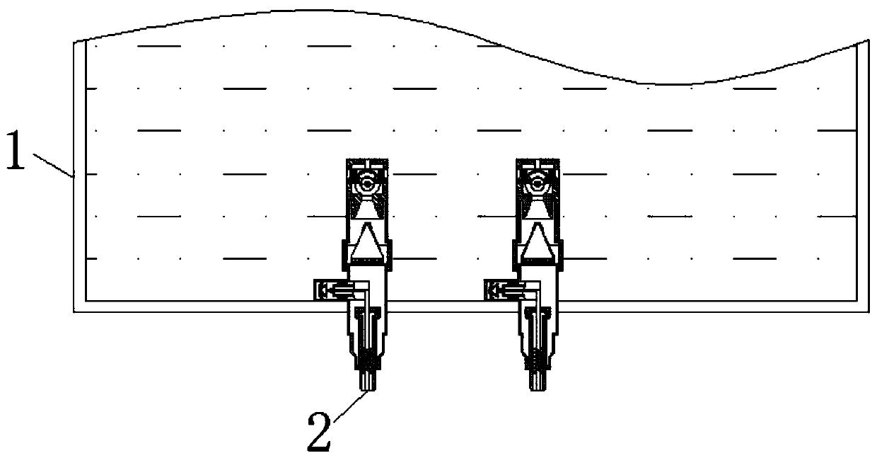
[0021] see Figure 1-4 , a printing ink defoaming device utilizing airflow positive pressure vibration, a printing ink defoaming equipment utilizing airflow positive pressure vibration, comprising an oil tank 1, the inside of the oil tank 1 is fixedly connected with an oil outlet mechanism 2, and the oil outlet mechanism 2 includes The oil outlet 3 is provided with an oil pipe 13 inside the oil outlet 3, and the inside of the oil outlet 3 and both sides of the...


PUM


Abstract

The invention relates to the technical field of printing ink, and in particular relates to printing ink defoaming equipment utilizing airflow positive pressure vibration. The equipment comprises an oil tank, and an oil outlet mechanism is fixedly connected inside the oil tank. The oil outlet mechanism comprises an oil outlet. An oil extraction port is fixedly connected at the upper part of the oiloutlet. A shell is fixedly connected at one end, remote from the oil outlet, of the oil extraction port. A defoaming mechanism is fixedly connected inside the shell. The defoaming mechanism comprisesan air outlet nozzle. And an air supply channel is fixedly connected inside the air outlet nozzle. An oil return channel is fixedly connected to the surface of the air supply channel, a hollow channel is fixedly connected to the upper part of the air outlet nozzle, and the shell is vibrated when fan blades rotate; because a vibration absorbing material is arranged between the shell and the oil outlet mechanism, the vibration does not affect the oil outlet mechanism. The vibration of the shell can cause ink in an ink tank to slightly vibrate, and at the same time, the top of the shell is accompanied by a flowing-out airflow, and the effect of separating flocculent substances can be achieved.

Description

technical field [0001] The invention relates to the technical field of printing ink, in particular to a printing ink defoaming device utilizing airflow positive pressure vibration. Background technique [0002] Printing is the technology of transferring the ink to the surface of paper, fabric, plastic, leather and other materials through the process of plate making, ink application and pressurization to copy the content of the original manuscript in batches. The quality directly determines the effect of printing. [0003] With the development of science and technology, the preparation of ink is becoming more and more precise, but in the process of ink filling, due to the high viscosity of ink and the high surface tension of ink, it is difficult for the gas in the ink to escape from the ink film and stay in the ink layer. In this way, air bubbles are generated in the ink. For the elimination of air bubbles, in the prior art, a vibrating device is often installed on the inner...

Claims


Application Information

Patent Timeline
IPC IPC(8): B01D19/00B41F31/00
CPCB01D19/0052B01D19/0078B41F31/00
Inventor 曹阳
Owner 东莞市南粤印刷有限公司
Learn More