On-load voltage regulation circuit of staggered parallel multi-gear transformer

A technology for voltage regulation circuits and transformers, applied in transformers, variable transformers, circuits, etc., can solve problems such as complex switch structures, and achieve the effect of reducing the number of openings and closings

Pending Publication Date: 2019-09-03
ZHEJIANG BOTHWELL ELECTRIC
View PDF4 Cites 0 Cited by
  • Summary
  • Abstract
  • Description
  • Claims
  • Application Information

AI Technical Summary

Problems solved by technology

The upper limit of its on-off times determines the service life of the voltage regulating switch designed according to this circuit." This defect remains unchanged.
And as the number of switch gears increases, the number of transition circuit selection switches also increases, and the switch structure tends to be complicated

Method used


Image

  • On-load voltage regulation circuit of staggered parallel multi-gear transformer
  • On-load voltage regulation circuit of staggered parallel multi-gear transformer

Examples


Embodiment Construction

[0056] The structural characteristics and working principle of the positive and negative voltage regulating circuit of the present invention will be further described below in conjunction with the accompanying drawings.

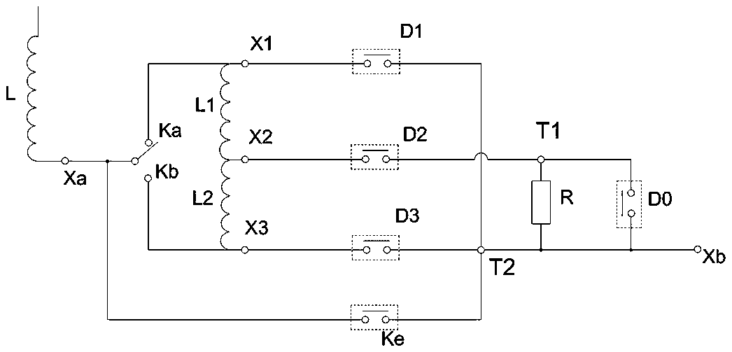
[0057] see figure 1 Shown is a schematic diagram of a five-speed transformer voltage regulating circuit under the technical solution of this aspect. The circuit is composed of a main winding, a voltage regulating winding, a rated voltage branch, a transition switching unit, and three voltage regulating branches.

[0058] The transition switching unit includes a first input terminal T1, a second input terminal T2, an output terminal Xb, and a vacuum interrupter D0 connected in series between the first input terminal T1 and the output terminal Xb in parallel with a transition resistor R.

[0059] The first voltage regulating coil L1 and the second voltage regulating coil L2 are connected end to end to form a voltage regulating winding, and a voltage regulating ...


PUM


Abstract

The invention relates to the field of distribution transformers, in particular to an on-load voltage regulation circuit of a staggered parallel multi-gear transformer. The on-load voltage regulation circuit comprises a main winding, a polarity reversing switch, a voltage regulation winding, a transition switching unit, a rated voltage branch and a plurality of voltage regulation branches. The polarity reversing switch is arranged between the main winding and the voltage regulation winding, and positive and negative voltage regulation is achieved by regulating the connection end of the independent contact of the polarity reversing switch; one end of each voltage regulation branch is connected to two end taps and the middle tap of the voltage regulation winding; the other ends of the voltageregulation branches are adjacent and staggered and arranged in parallel into two groups which are respectively connected with the two input ends of the transition switching unit, the input end of therated voltage branch is connected with the output end of the main winding, and the output end of the rated voltage branch is connected with the output end of the voltage regulation circuit. The on-off frequency of the on-off switch is reduced, the service life of the corresponding voltage regulation switch is prolonged, the transition voltage changes along with a voltage regulation gear in the voltage regulation process, and gear skipping and voltage regulation are not needed.

Description

technical field [0001] The invention relates to the field of distribution and transformation transformers, in particular to an on-load positive and negative voltage regulation circuit. Background technique [0002] In the patent with the application number 201610121960 and the title: "A Permanent Magnet Vacuum On-Load Voltage Regulator, Transformer and On-Load Voltage Regulation Method", it provides a method of using two vacuum interrupters to form the main circuit and the transition circuit respectively. Structural on-load voltage regulation method. The key points of this technical solution are: during normal operation, the vacuum interrupter of the main circuit is connected, the main circuit is in the connected state, the vacuum interrupter of the transition circuit is disconnected, the transition circuit is in the disconnected state, The voltage winding determines the external voltage supply gear of the circuit. When the gear is switched, the transition circuit vacuum i...

Claims


Application Information

Patent Timeline
IPC IPC(8): H02P13/06H01F29/04H01H9/00
CPCH02P13/06H01F29/04H01H9/0038
Inventor 吴正文姜方军
Owner ZHEJIANG BOTHWELL ELECTRIC
Why Eureka
Try Eureka