
Pantograph contact point real-time detection algorithm based on monocular infrared image

An infrared image and real-time detection technology, applied in the field of traffic safety engineering, can solve the problem of not being able to highlight the characteristics of contact lines and pantographs

Active Publication Date: 2019-09-03
WUHAN INSTITUTE OF TECHNOLOGY
View PDF3 Cites 3 Cited by
  • Summary
  • Abstract
  • Description
  • Claims
  • Application Information

AI Technical Summary

Problems solved by technology

[0005] Aiming at the defects or deficiencies of the traditional technology, the present invention proposes a real-time contact point detection algorithm based on monocular infrared images, which effectively solves the problem that the traditional edge detection operator treats pantograph and contact line contours indiscriminately, and cannot highlight the contact points well. Characteristic of lines and pantographs and problems with lots of background edges

Method used


Image

  • Pantograph contact point real-time detection algorithm based on monocular infrared image
  • Pantograph contact point real-time detection algorithm based on monocular infrared image
  • Pantograph contact point real-time detection algorithm based on monocular infrared image

Examples


Embodiment 1

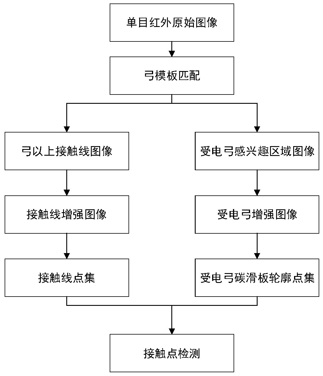
[0058] like figure 1 Shown is a flow chart of a real-time contact point detection algorithm based on a monocular infrared image provided by an embodiment of the present invention, including the following steps:

[0059] S1. Use the bow template intercepted from the first original image of the infrared video frame sequence to perform template matching on the monocular infrared original image acquired in real time to determine the position of the pantograph;

[0060] S2. According to the position of the pantograph, the image of the contact line above the bow and the image of the region of interest of the pantograph are respectively extracted from the monocular infrared original image;

[0061] S3. Perform image enhancement operations on the contact line image above the bow and the pantograph image of interest respectively, to obtain the enhanced contact line image and the enhanced image of the pantograph;

[0062] S4, carry out pixel normalization operation and parameter optimi...

Embodiment 2

[0065] Based on the principle of Embodiment 1, this embodiment illustrates the implementation method of the above steps by way of example.

[0066] Step S1, use the bow template intercepted from the first original image of the infrared video frame sequence to perform template matching on the monocular infrared original image acquired in real time, and determine the position of the pantograph.

[0067] Exemplarily, a near-infrared camera and a high-definition visible light camera can be used to obtain real-time monocular infrared original images captured by the camera while the locomotive is moving, and use the bow template intercepted from the first original image of the infrared video frame sequence to analyze the monocular infrared original The pantograph in the image is matched to realize the positioning of the pantograph. The positioning rectangle of the pantograph obtained by template matching is (X, Y, W, H), where (X, Y) is the coordinates of the upper left corner of th...


PUM


Abstract

The invention discloses a contact point real-time detection algorithm based on a monocular infrared image. The method comprises the steps of using a bow template intercepted from a first original image of an infrared video frame sequence for carrying out template matching on a monocular infrared original image obtained in real time, and determining the position of a pantograph; according to the position of the pantograph, respectively extracting an image of a contact line above the pantograph and an image of an area of interest of the pantograph from the monocular infrared original image; respectively performing image enhancement operation on the contact line image above the bow and the image of interest of the pantograph to obtain a contact line enhanced image and a pantograph enhanced image; performing pixel normalization operation and parameter optimization on the contact line enhanced image and the pantograph enhanced image respectively, and extracting a contact line point set anda pantograph carbon slide plate contour point set; and respectively carrying out linear parameter estimation on the contact line point set and the pantograph carbon slide plate contour point set, andcalculating an intersection point of a contact line fitting straight line and a pantograph slide plate fitting straight line to realize the contact point positioning.

Description

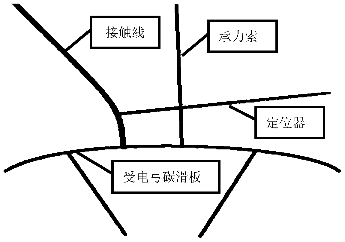
technical field [0001] The invention relates to the technical field of traffic safety engineering, in particular to a real-time detection algorithm of a contact point based on a monocular infrared image. Background technique [0002] The electric locomotive draws electric energy from the catenary wire through the pantograph to pull the train forward. The pantograph on the roof of the train will automatically rise and fall during the running of the train so that the sliding plate on the top of the pantograph and the contact wire in the catenary can be kept in good condition. Contact, and in order to improve the service life of the skateboard and prevent the contact line from continuing to rub against a certain part of the skateboard when the train is running, people set up the contact line in a "zigzag" manner so that the contact line can go back and forth within the effective range of the skateboard Sliding, the height of the contact line should also match the maximum height...

Claims


Application Information

Patent Timeline
IPC IPC(8): G06T7/13G06T5/40
CPCG06T7/13G06T5/40G06T2207/30108
Inventor 黄正华王硕孙建国李璇黄振洪汉玉张天序
Owner WUHAN INSTITUTE OF TECHNOLOGY
Learn More