A time-optimal trajectory planning method for robot path tracking

A trajectory planning and time-optimized technology, applied to instruments, two-dimensional position/course control, vehicle position/route/altitude control, etc., can solve difficult integration, inaccurate dynamic models, and increase trajectory planning calculations Time and other issues, to achieve the effect of reducing the number of planning points and reducing planning time

Inactive Publication Date: 2021-12-14
SOUTH CHINA UNIV OF TECH +1
View PDF4 Cites 0 Cited by
  • Summary
  • Abstract
  • Description
  • Claims
  • Application Information

AI Technical Summary

Problems solved by technology

[0003] Since the 1980s, the time-optimal control method has been proposed in many papers and is well known. Among them, the most widely used numerical integration method is difficult to integrate in the face of complex dynamic model calculations, especially nonlinear dynamic models, resulting in It can only be applied to the simple dynamic model, which leads to the inaccuracy of the dynamic model
At the same time, each control cycle of numerical integration needs to be planned by solving dynamic and kinematic constraints, which greatly increases the calculation time of trajectory planning.

Method used


Image

  • A time-optimal trajectory planning method for robot path tracking
  • A time-optimal trajectory planning method for robot path tracking
  • A time-optimal trajectory planning method for robot path tracking

Examples


Embodiment Construction

[0100] By the following specific examples for the purposes of the present invention are described in further detail, examples not attempting to repeat, but the embodiment of the present invention is therefore not limited to the following examples.

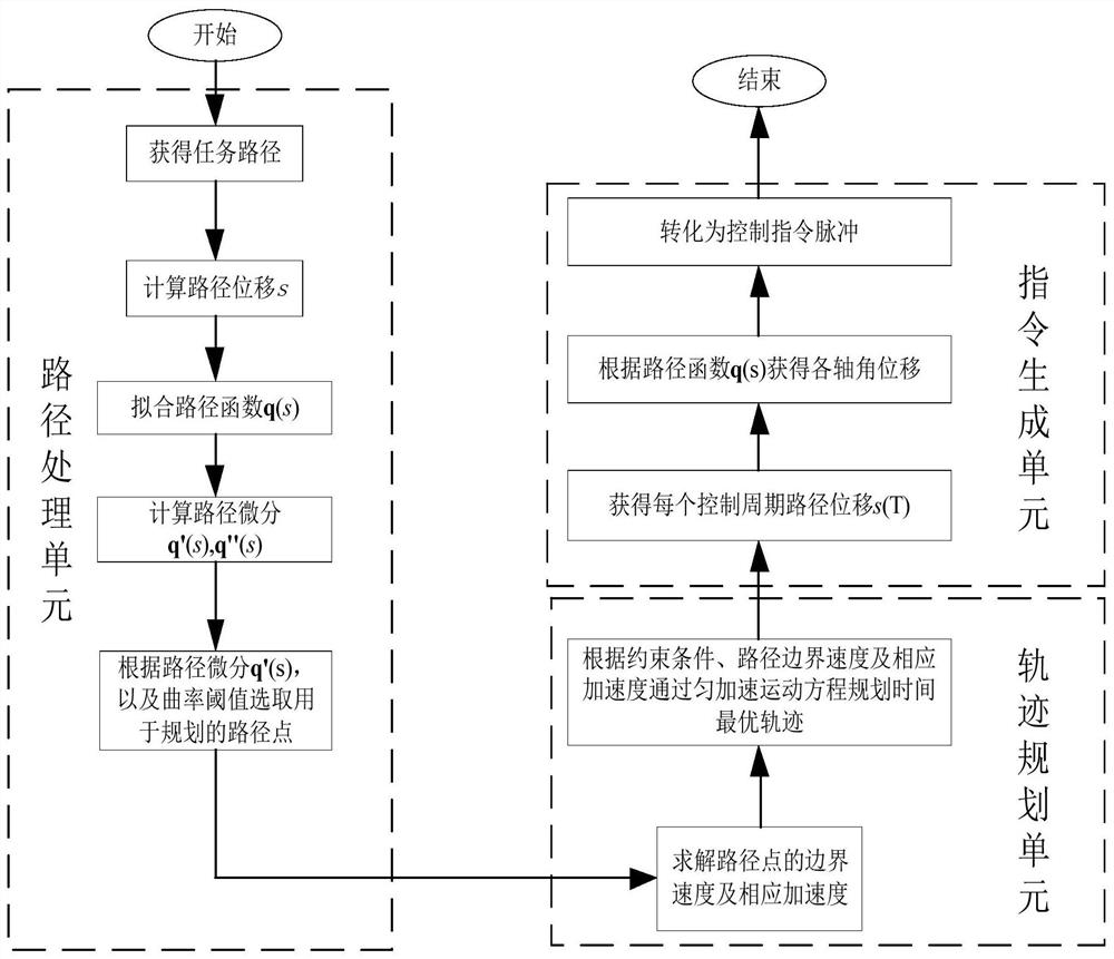
[0101] like figure 1 A method for time tracking robot path planning system illustrated optimal trajectory, the system comprising a processing unit path, trajectory planning unit and instruction generating unit;

[0102] Wherein the path calculation processing unit executes displacement processing path, the path function fitting process, the differential coefficient calculation processing path planning and path point extraction processing;

[0103] Trajectory planning means for optimal trajectory path between the displacement speed of the floor plan of the robot, planning point of assuming constant acceleration, constant acceleration by equation planning;

[0104] The instruction generating unit for obtaining the optimal trajectory, the...


PUM


Abstract

The invention discloses a time-optimal trajectory planning system and method for robot path tracking. The system includes a path processing unit, a trajectory planning unit and an instruction generation unit; the path processing unit executes path displacement calculation processing and path function fitting processing , path differential coefficient calculation processing and path planning point selection processing; the trajectory planning unit is used to plan the optimal trajectory; the instruction generation unit is used to generate control instructions and the like. The method comprises the following steps: S1 calculation and processing of path displacement; S2 obtaining path function; S3 calculation and processing of path differential coefficient; S4 selection of path planning points; path displacement of each control cycle; S8 obtains the angular displacement of each axis at each moment; S9 the angular displacement of each axis will be converted into a control command pulse signal and so on. The invention reduces path tracking time and calculation time of trajectory planning.

Description

technical field [0001] The invention relates to the technical field of robot automatic control, in particular to a time-optimal trajectory planning system and method for robot path tracking. Background technique [0002] When using robots for handling, assembly, machining and other tasks, when using robots for task path tracking, in order to improve the working efficiency of robots, the robots should be run at high speeds. . The traditional S-type speed planning cannot give full play to the performance of the motor. In order to make the robot work at the maximum allowable speed all the time, the trajectory planning method that makes the robot move under critical conditions is called the time-optimal trajectory planning method. [0003] Since the 1980s, the time-optimal control method has been proposed in many papers and is well known. Among them, the most widely used numerical integration method is difficult to integrate in the face of complex dynamic model calculations, e...

Claims


Application Information

Patent Timeline
Patent Type & Authority Patents(China)
IPC IPC(8): G05D1/02
CPCG05D1/0223
Inventor 李琳肖佳栋张铁邹焱飚
Owner SOUTH CHINA UNIV OF TECH
Why Eureka
Try Eureka