Region of interest placement for quantitative ultrasound imaging

A region of interest, ultrasonic imaging technology, applied in ultrasonic/sonic/infrasound image/data processing, ultrasonic/sonic/infrasonic diagnosis, ultrasonic/sonic/infrasound equipment control, etc., can solve the problem of irreproducible, low image quality And other issues

Active Publication Date: 2019-09-03
SIEMENS MEDICAL SOLUTIONS USA INC
View PDF6 Cites 2 Cited by
  • Summary
  • Abstract
  • Description
  • Claims
  • Application Information

AI Technical Summary

Problems solved by technology

Errors when resizing ROIs can also lead to low image quality and / or non-reproducible results

Method used


Image

  • Region of interest placement for quantitative ultrasound imaging
  • Region of interest placement for quantitative ultrasound imaging
  • Region of interest placement for quantitative ultrasound imaging

Examples


Embodiment Construction

[0012] Provides automatic ROI placement in shear wave or other quantitative imaging. Application of signal processing, image processing, and / or machine learning networks automatically locates, resizes, and / or adjusts the shape of ROIs, such as for shear wave velocity imaging or other acoustic radiation force pulse-based ultrasound imaging. For example, in shear wave imaging, ROIs are localized for obtaining individual ROI-based shear wave velocity measurements or for real-time shear wave velocity spatial imaging for two-dimensional or three-dimensional regions.

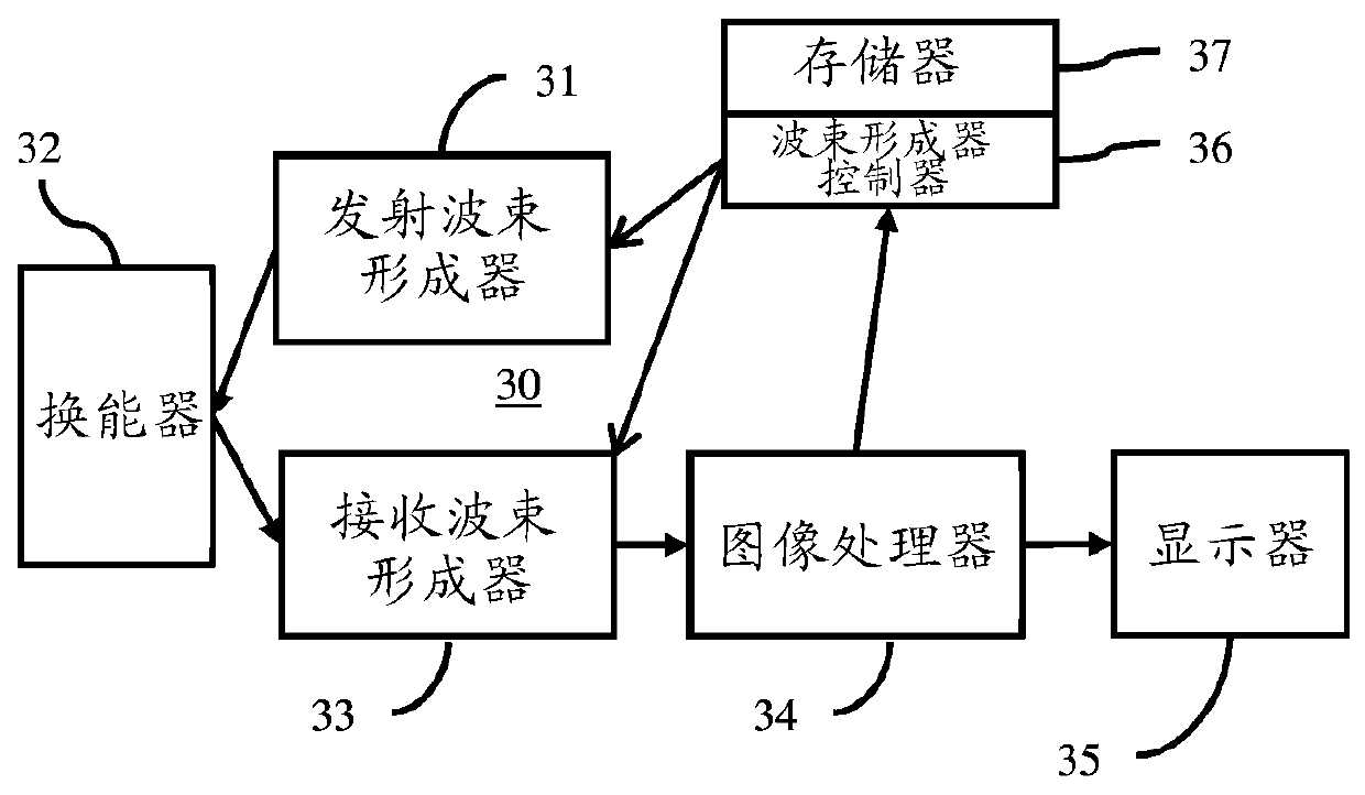
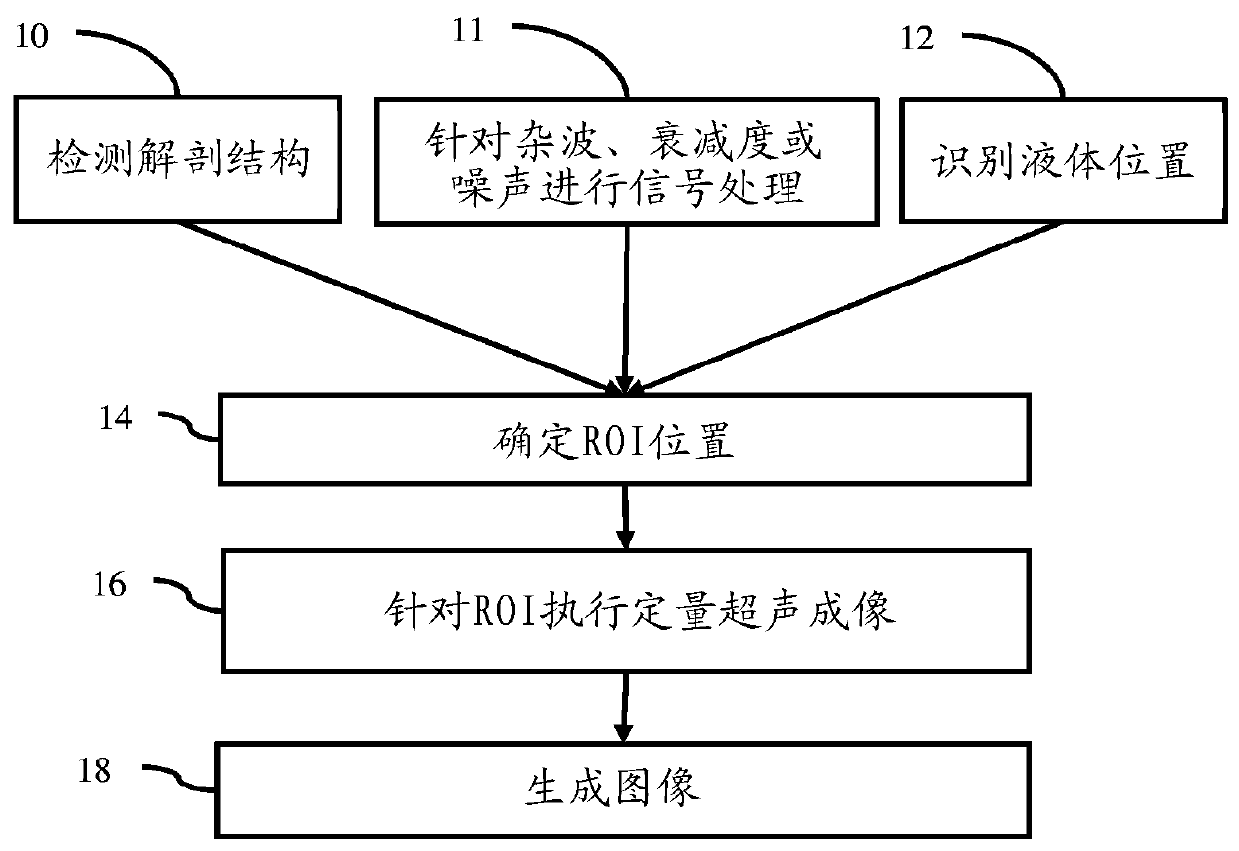
[0013] figure 1 One embodiment of a method for quantifying ROI placement in ultrasound imaging using an ultrasound scanner is shown. In general, ROIs for quantitative ultrasound imaging are automatically placed using: spacing the ROI location from the object of interest, signal processing on in-phase and quadrature (I / Q) or radio frequency (RF) data, and / or locations to avoid (e.g. liquid locations).

[0014] This...


PUM


Abstract

The invention relates to region of interest placement for quantitative ultrasound imaging. For region of interest (ROI) placement in quantitative ultrasound imaging with an ultrasound scanner (30), the ROI is automatically placed (14) using anatomy detection (10) specific to the quantification, signal processing (11) for clutter, attenuation, or noise, and / or identification (12) of regions of fluid. For quantification, multiple ROIs may be positioned automatically (14). The automatic placement (14) may improve consistency of measures over time and between sonographers and may provide for better image quality with less influence from undesired signals. As a result, diagnosis and / or treatment may be improved.

Description

Background technique [0001] The present invention relates to quantifying ultrasound imaging. In quantitative ultrasound imaging, the detected information is further processed to quantify properties of the imaged tissue. Rather than just providing a B-mode image of tissue, it is imaging properties of that tissue. For example, ultrasound imaging is used to calculate shear wave velocity in tissue. Other examples include strain, attenuation or backscatter measurements. [0002] For quantitative ultrasound imaging, users typically locate a region of interest (ROI) in a B-mode image. The ROI defines the region for which quantification is performed. To avoid delays or processing complications of performing quantification over the entire field of view (FOV) of a B-mode image, a user-localized ROI defines the tissue region used for quantification. This manual ROI positioning hinders workflow and increases scan time. Furthermore, operator dependence and suboptimal ROI localization...

Claims


Application Information

Patent Timeline
Patent Type & Authority Applications(China)
IPC IPC(8): A61B8/00A61B8/08
CPCA61B8/5207A61B8/469A61B8/5269A61B8/54A61B8/5223A61B8/085G06N20/20G06N20/10G06N3/08G16H50/30G06N5/01G06N7/01A61B8/4477G06T2207/10132A61B8/461G06T2207/20084G06T7/0012G06N20/00G06T2207/20104
Inventor Y.拉拜德
Owner SIEMENS MEDICAL SOLUTIONS USA INC
Why Eureka
Try Eureka