
Winding machine and winding mechanism

A winding mechanism and winding technology, applied in the direction of coil manufacturing, etc., can solve problems such as programming complexity, coordination deviation, equipment damage, etc., and achieve the effect of high-speed interspersed fit

Pending Publication Date: 2019-08-30
何子全
View PDF0 Cites 2 Cited by
  • Summary
  • Abstract
  • Description
  • Claims
  • Application Information

AI Technical Summary

Problems solved by technology

[0005] The purpose of the present invention is to provide a winding machine and its winding mechanism, which aims to solve the problem of complex programming, slow winding speed, low production efficiency, and even equipment damage due to deviations in coordination of the toroidal core coil winding machine in the prior art technical issues

Method used


Image

  • Winding machine and winding mechanism
  • Winding machine and winding mechanism
  • Winding machine and winding mechanism

Examples


Embodiment Construction

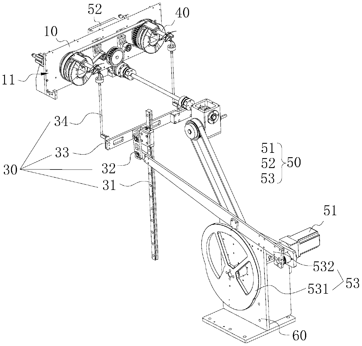
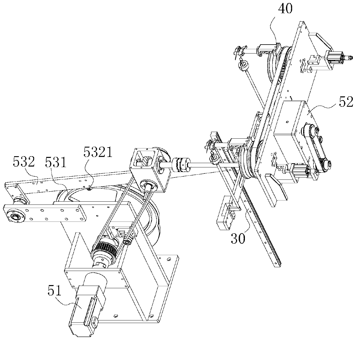
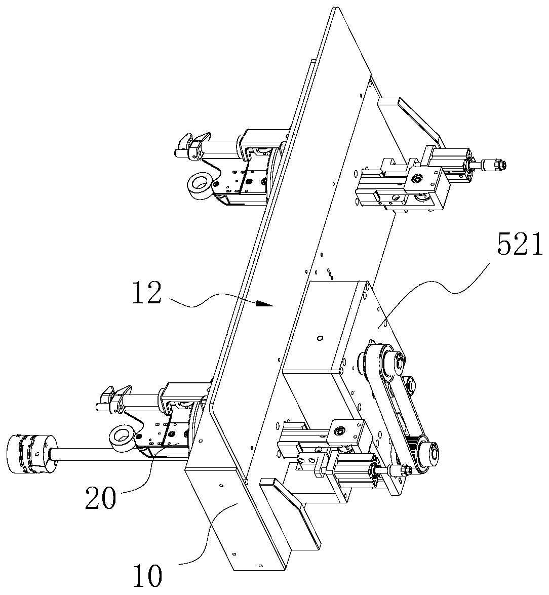
[0057] Embodiments of the present invention are described in detail below, examples of which are shown in the drawings, wherein the same or similar reference numerals designate the same or similar elements or elements having the same or similar functions throughout. Attached below by reference Figure 1-15 The described embodiments are exemplary, and are intended to explain the embodiments of the present invention, and should not be construed as limitations of the present invention.

[0058] In the description of the embodiments of the present invention, it should be understood that if the terms "length", "width", "upper", "lower", "front", "rear", "left", "right", " The orientation or positional relationship indicated by "vertical", "horizontal", "top", "bottom", "inner", "outer", etc. is based on the orientation or positional relationship shown in the drawings, and is only for the convenience of describing the embodiment of the present invention and simplified descriptions,...


PUM


Abstract

The invention belongs to the technical field of annular inductance coil production equipment, and particularly relates to a winding machine and a winding mechanism. The winding mechanism comprises a wire hooking component by taking a swing arm cam mechanism as a main body, a winding component transmission device by taking an incomplete gear mechanism as a middle connecting component, a rotary winding device used for controlling a winding rotary clamping jaw through a cylindrical end face cam, and a servo motor group used for driving the three parts to operate. The servo motor group drives theincomplete gear mechanism to rotate and the swing arm mechanism to operate, so that the winding rotary clamping jaw component and the wire hooking crochet hook respectively perform intermittent rotating winding motion and variable-speed crochet hook reciprocating motion, and further complex combined motion conforming to a crochet hook type winding production process is formed, high-speed interpenetration matching of wire hooking and winding is achieved, the annular iron core is quickly and orderly hooked and wound, and the production efficiency and the stability of equipment are greatly improved.

Description

technical field [0001] The invention belongs to the technical field of annular inductance coil production equipment, and in particular relates to a winding machine and a winding mechanism thereof. Background technique [0002] Ring inductors are commonly used anti-interference components in electronic circuits. They have a good suppression effect on high-frequency noise and are widely used in power conversion and line filters; for the production of ring inductors with small inner holes and relatively thick wire diameters Generally, it is done manually by manually using a crochet needle to wind the metal wire round and round on the annular iron core. A product often needs to be wound manually and mechanically for dozens of times. The production needs to repeat tens of thousands of manual actions. Moreover, there is an error in the number of coils in manual work, and the spacing between the wires is uneven, which affects the quality of the product. [0003] Therefore, an aut...

Claims


Application Information

Patent Timeline
IPC IPC(8): H01F41/08
CPCH01F41/08
Inventor 何子全
Owner 何子全
Learn More