
Resistor fixture and resistance regulator

A resistance and fixture technology, applied in resistors, measuring resistance/reactance/impedance, resistance manufacturing, etc., can solve problems such as limited assembly space and inability to detect resistance values ​​to be measured.

Pending Publication Date: 2019-08-30
SHENZHEN JPT OPTO ELECTRONICS CO LTD
View PDF0 Cites 3 Cited by
  • Summary
  • Abstract
  • Description
  • Claims
  • Application Information

AI Technical Summary

Problems solved by technology

[0003] The purpose of this application is to provide a resistance jig and a resistance adjustment machine, to a certain extent solve the technical problem that the detection component cannot detect the resistance value of the resistance to be measured due to the limited assembly space when a high-power laser is used for cutting

Method used

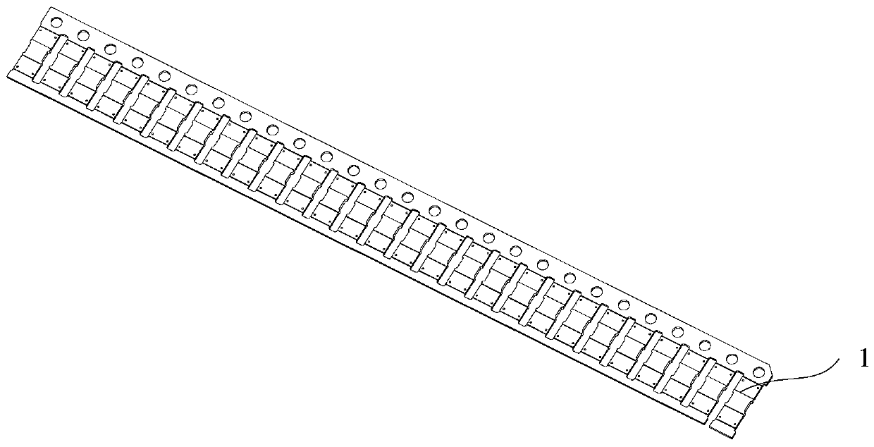
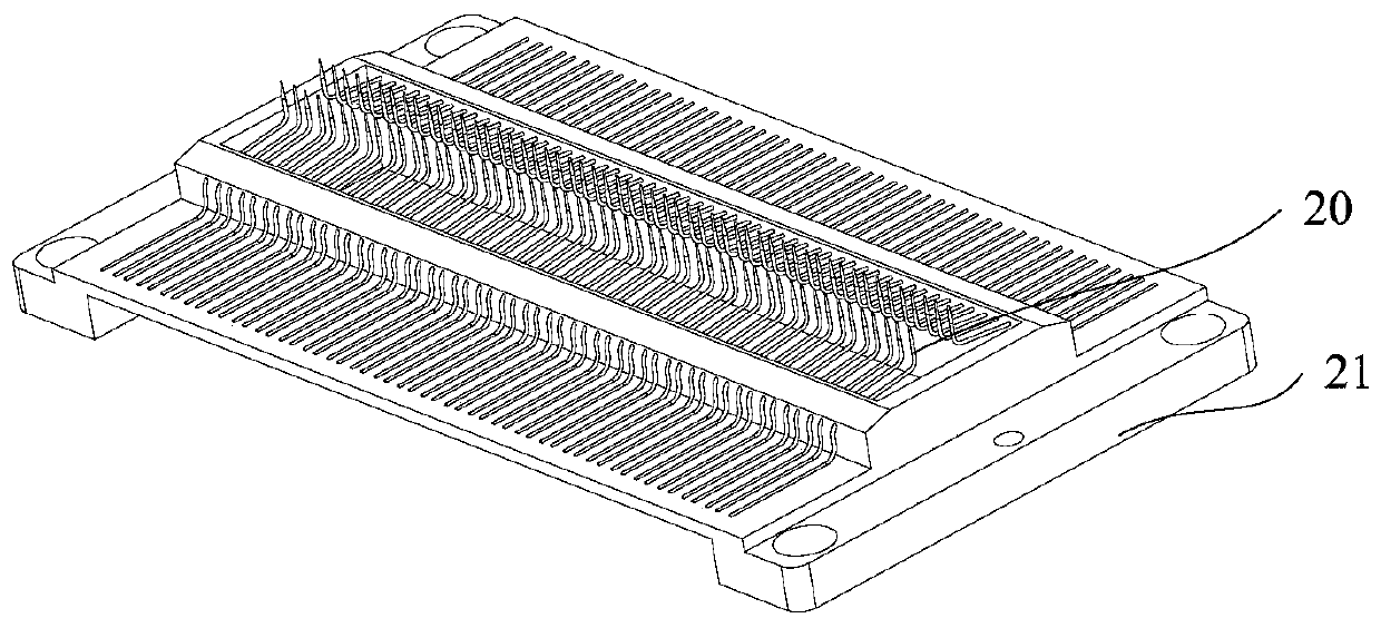
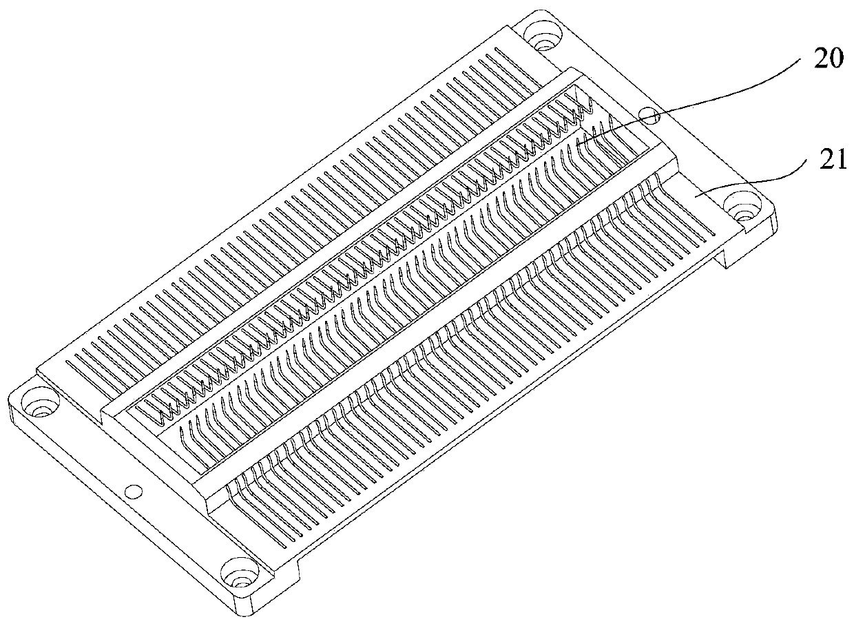

Image

  • Resistor fixture and resistance regulator
  • Resistor fixture and resistance regulator
  • Resistor fixture and resistance regulator

Examples


Embodiment Construction

[0035] The technical solutions of the present application will be clearly and completely described below in conjunction with the accompanying drawings. Apparently, the described embodiments are some of the embodiments of the present application, not all of them. Based on the embodiments in this application, all other embodiments obtained by persons of ordinary skill in the art without making creative efforts belong to the scope of protection of this application.

[0036] In the description of this application, it should be noted that the terms "center", "upper", "lower", "left", "right", "vertical", "horizontal", "inner", "outer" etc. The indicated orientation or positional relationship is based on the orientation or positional relationship shown in the drawings, and is only for the convenience of describing the present application and simplifying the description, rather than indicating or implying that the referred device or element must have a specific orientation, use a spec...


PUM


Abstract

The application provides a resistor fixture and a resistance regulator, which relate to the technical field of laser cutting. The technical problem that a detection component cannot detect the resistance value of a resistor to be detected during laser cutting due to limited assembly space is solved to a certain extent. The resistor fixture includes a frame, a detection component arranged inside the frame and a drive component capable of driving the detection component to move close to or away from a resistor to be detected. A cutting member used for cutting the resistor to be detected and thedetection component are located on two opposite sides of the resistor to be detected. The resistor fixture is applicable to laser cutting of resistors. When a laser head is used to cut the resistor, the laser head is close to the resistor. If the detection component and the cutting member are conventionally arranged on the same side of the resistor to be detected, the resistance value of the resistor cannot be accurately detected. In the application, the cutting member used for cutting the resistor to be detected and the detection component are located on two opposite sides of the resistor tobe detected, and the resistance value can be accurately detected.

Description

technical field [0001] The present application relates to the technical field of laser cutting, in particular to a resistance jig and a resistance adjusting machine. Background technique [0002] In the resistance production industry, it is often necessary to micro-cut the resistance and fine-tune the resistance value; when a high-power laser is used to cut the resistance to be tested, if the traditional installation method is used, due to the limited assembly space, the detection component cannot be used to measure the resistance. Check the resistance value. Contents of the invention [0003] The purpose of this application is to provide a resistance jig and a resistance adjustment machine, to a certain extent solve the technical problem that the detection component cannot detect the resistance value of the resistance to be measured due to the limited assembly space when a high-power laser is used for cutting . [0004] A resistance fixture provided by the present appli...

Claims


Application Information

Patent Timeline
IPC IPC(8): H01C17/00H01C17/242G01R27/02
CPCH01C17/00H01C17/242G01R27/02
Inventor 许根夫
Owner SHENZHEN JPT OPTO ELECTRONICS CO LTD
Learn More