


Quick Research
Generate reliable direction feasibility study reports for your R&D in just a few steps.

Technical Q&A
Discover and master advanced knowledge NOW. Basics, ideas, possibilities, all at once.

Find Solutions
As an expert in R&D theories, this can generate solutions to your technical problems instantly.

Evaluate Feasibility
Analyze your overall solution with one click, know your potential R&D risks in advance.

Monitor Landscape
Get weekly tech updates, stay abreast of the latest tech innovations and key insights.
A file binding device
A file and work board technology, used in metal processing and other directions, can solve problems such as operator injury
- Summary
- Abstract
- Description
- Claims
- Application Information
AI Technical Summary
Problems solved by technology
Method used
Image

Examples
Embodiment 1
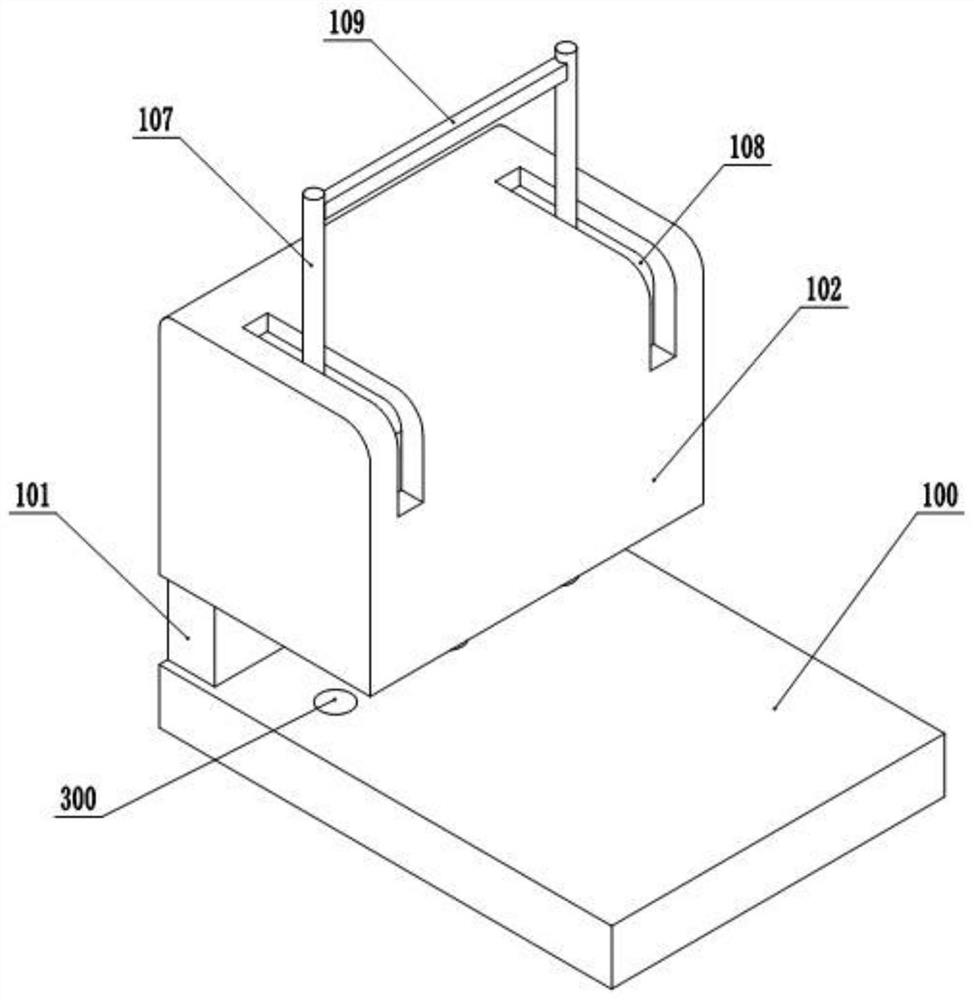
[0037] Embodiment 1 is basically as attached figure 1 Shown:
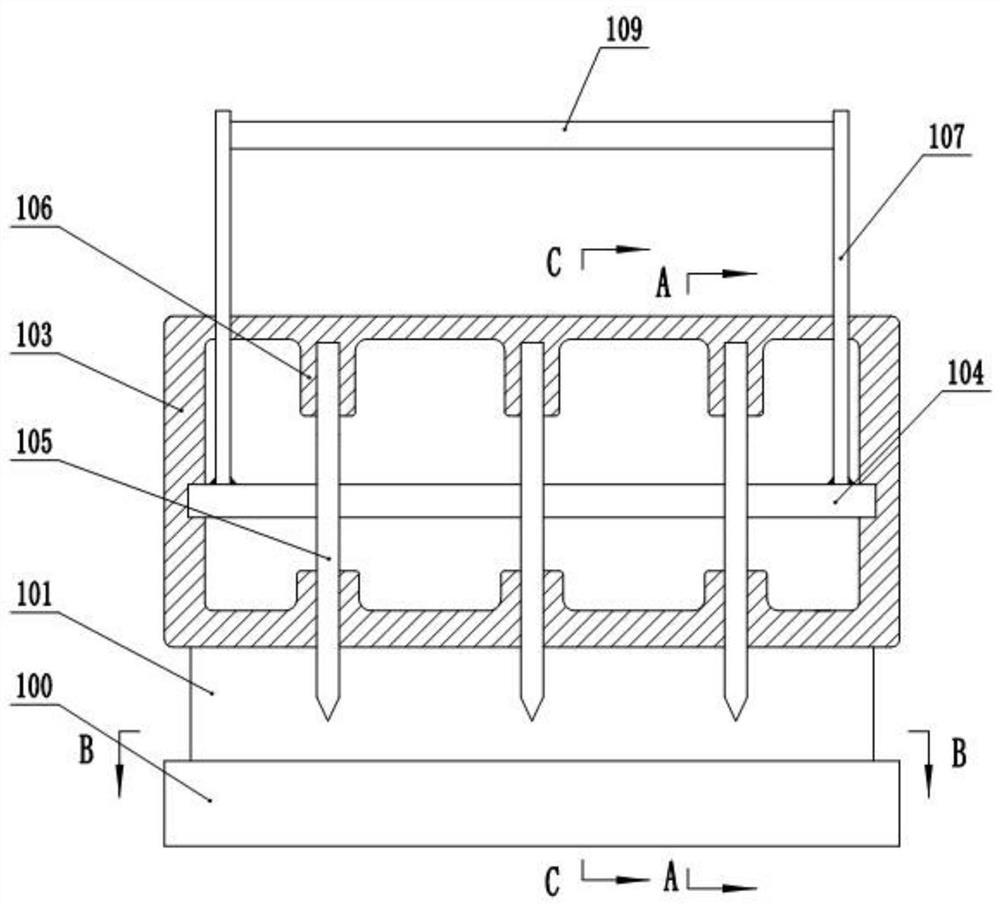
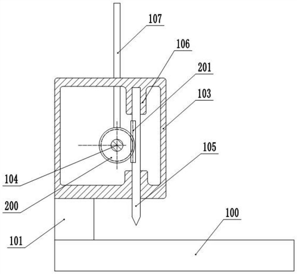
[0038] A file binding device, comprising a horizontally arranged workboard 100, a baffle 101 is vertically fixed on one side of the workboard 100, a puncher 102 is fixed on the top of the baffle 101, and a hole punch 102 is formed between the puncher 102 and the workboard 100. Openings for files to drop in, such as figure 2 As shown, the punching machine 102 includes a hollow housing 103, the housing 103 is rotatably connected with a horizontal shaft 104, and the housing 103 is vertically slidingly connected with three punching nails 105, and the three punching nails 105 are on the same straight line , and the straight line is parallel to the horizontal axis 104, the specific setting of the perforated nail 105 is as follows: a connecting seat 106 is integrally formed on the inner top wall of the housing 103, a chute is vertically opened in the connecting seat 106, and the top of the perforated nail 105 Slidingly...
Embodiment 2
[0046] Embodiment 2 is basically as Figure 6 Shown:
[0047] The difference between embodiment 2 and embodiment 1 is that: an adsorption channel 400 is also provided in the working plate 100, the left end of the adsorption channel 400 is closed, and each hole 300 is connected with the adsorption channel 400, combined with Figure 7 As shown, the connection between the adsorption channel 400 and the hole groove 300 is the necking section 401, and the diameter of the necking section 401 is smaller than the diameter of the adsorption channel 400, and the diameter of the hole groove 300 is 0.2-0.5 mm larger than the diameter of the hole nail.
[0048] On the side wall of the cavity 304, there is also a suction pipe 402 connected to the upper cavity 305 and the adsorption channel 400, and an air intake check valve II is arranged on the suction pipe 402. When the volume in the upper cavity 305 increases , when the air pressure decreases, the intake check valve II opens, and the ga...
PUM
 Abstract
Description
Claims
Application Information
 - R&D Engineer
- R&D Manager
- IP Professional
- Industry Leading Data Capabilities
- Powerful AI technology
- Patent DNA Extraction
Browse by: Latest US Patents, China's latest patents, Technical Efficacy Thesaurus, Application Domain, Technology Topic, Popular Technical Reports.
© 2024 PatSnap. All rights reserved.Legal|Privacy policy|Modern Slavery Act Transparency Statement|Sitemap|About US| Contact US: help@patsnap.com