Motor stator and rotor assembling tool

A technology for assembling tooling and stators and rotors, applied in the direction of centering/balancing rotors, etc., can solve problems such as difficulty in ensuring assembly quality, and achieve the effect of precise assembly

Inactive Publication Date: 2019-08-27
ANHUI JIANGHUAI AUTOMOBILE GRP CORP LTD
View PDF5 Cites 0 Cited by
  • Summary
  • Abstract
  • Description
  • Claims
  • Application Information

AI Technical Summary

Problems solved by technology

[0004] The main purpose of the present invention is to propose a motor stator and rotor assembly tool, which aims to solve the problem that the rotor is eccentric due to the magnetic field suction when the existing assembly tool is assembling the rotor and the stator, which makes it difficult to ensure the assembly quality.

Method used


Image

  • Motor stator and rotor assembling tool
  • Motor stator and rotor assembling tool
  • Motor stator and rotor assembling tool

Examples


Embodiment Construction

[0034] The following will clearly and completely describe the technical solutions in the embodiments of the present invention with reference to the accompanying drawings in the embodiments of the present invention. Obviously, the described embodiments are only part of the embodiments of the present invention, not all of them. Based on the embodiments of the present invention, all other embodiments obtained by persons of ordinary skill in the art without creative efforts fall within the protection scope of the present invention.

[0035] It should be noted that if there is a directional indication (such as up, down, left, right, front, back...) in the embodiment of the present invention, the directional indication is only used to explain the position in a certain posture (as shown in the accompanying drawing). If the specific posture changes, the directional indication will also change accordingly.

[0036] In addition, if there are descriptions involving "first", "second" and ...


PUM


Abstract

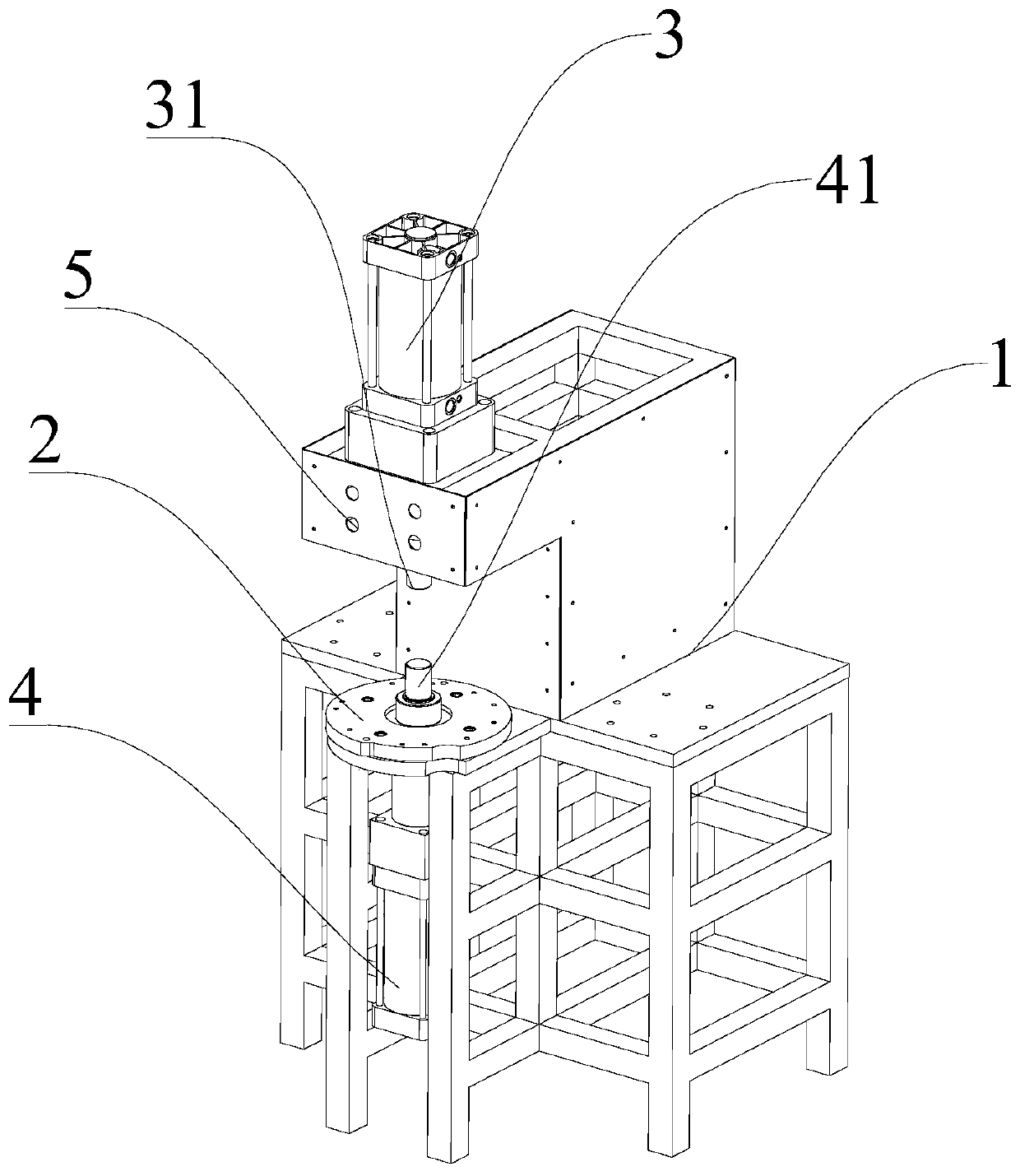
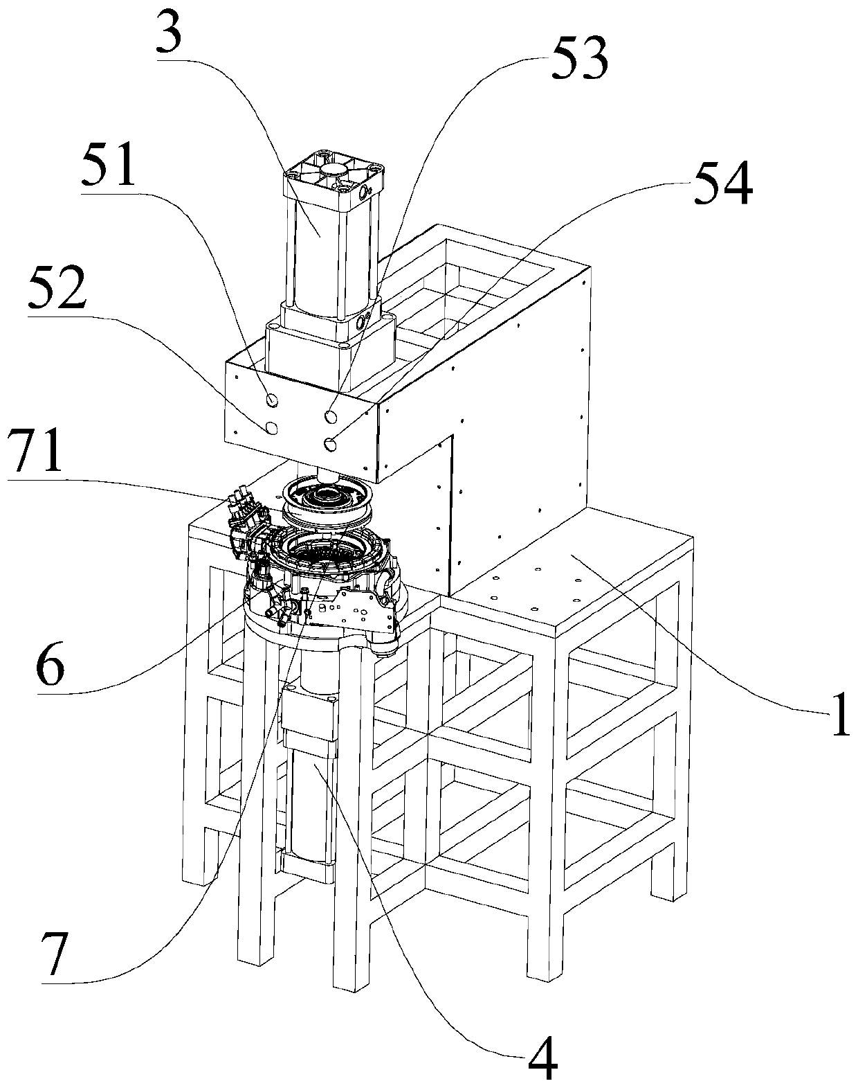
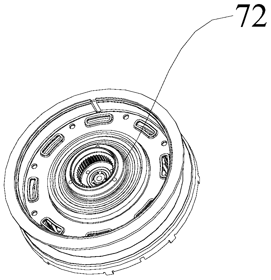
The invention discloses a motor stator and rotor assembling tool, and relates to the field of assembling equipment; the motor stator and rotor assembling tool comprises a supporting body, a connectingplate, a first air cylinder and a second air cylinder, wherein the connecting plate is arranged on the supporting body, and the upper end of the connecting plate is matched with a stator; the first air cylinder is arranged on the supporting body above the connecting plate; the bottom end of the first air cylinder is fixedly connected with a first guide rod, and the bottom end of the first guide rod extends towards the direction of the connecting plate, and is in contact fit with the upper end surface of a rotor; the second air cylinder is arranged on the supporting body below the connecting plate; the top end of the second air cylinder is fixedly connected with a second guide rod, and the top end of the second guide rod extends towards the direction of the connecting plate and is in contact fit with the lower end surface of the rotor; and under the driving of the first air cylinder and the second air cylinder, the first guide rod and the second guide rod clamp the rotor and move up and down in the vertical direction of the first guide rod and the second guide rod. When the tool is adopted in the motor stator and rotor assembly works, fixed-point movement of the rotor can be realized, and the rotor is prevented from shifting due to the suction force of a magnetic field.

Description

technical field [0001] The invention relates to the field of assembly equipment, in particular to the field of motor stator and rotor assembly equipment, in particular to a motor stator and rotor assembly tooling. Background technique [0002] At present, there are more and more applications of motors, especially permanent magnet synchronous motors, which can establish the magnetic field required for energy mutual conversion after pre-magnetization without external energy. The structure of the permanent magnet synchronous motor is relatively simple, but at the same time, due to its strong magnetism, the stator and rotor of the motor are prone to suction during assembly, which makes the assembly difficult and the assembly quality is difficult to guarantee; moreover, the personnel operation during the assembly process is also very difficult. great danger. Therefore, special stator and rotor assembly tooling is required to achieve assembly. [0003] The invention patent with ...

Claims


Application Information

Patent Timeline
Patent Type & Authority Applications(China)
IPC IPC(8): H02K15/16
CPCH02K15/16
Inventor 汤玉辉付林郭振
Owner ANHUI JIANGHUAI AUTOMOBILE GRP CORP LTD
Why Eureka
Try Eureka