
Calibration method and device for on-orbit emissivity of satellite-borne microwave imager antenna

A spaceborne microwave and microwave imaging technology, applied in the field of aerospace remote sensing, can solve problems such as inaccuracy, deviation from reality, and no on-orbit correction

Pending Publication Date: 2019-08-27
SHANGHAI SPACEFLIGHT INST OF TT&C & TELECOMM
View PDF4 Cites 2 Cited by
  • Summary
  • Abstract
  • Description
  • Claims
  • Application Information

AI Technical Summary

Problems solved by technology

[0003] In the process of traditional calibration, the emissivity of the main antenna is difficult to measure in the ground test engineering. Usually, the emissivity of the main antenna is calculated according to the ideal formula during spaceborne calibration, and its value has not been corrected on the orbit. There are shortcomings such as inaccuracy and deviation from reality

Method used


Image

  • Calibration method and device for on-orbit emissivity of satellite-borne microwave imager antenna
  • Calibration method and device for on-orbit emissivity of satellite-borne microwave imager antenna
  • Calibration method and device for on-orbit emissivity of satellite-borne microwave imager antenna

Examples


Embodiment 1

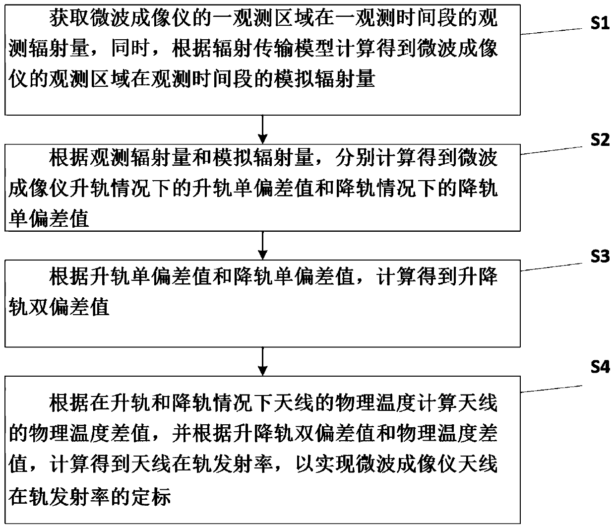
[0062] see figure 1 , the present embodiment provides a method for calibrating the on-orbit emissivity of a spaceborne microwave imager antenna, comprising the following steps:

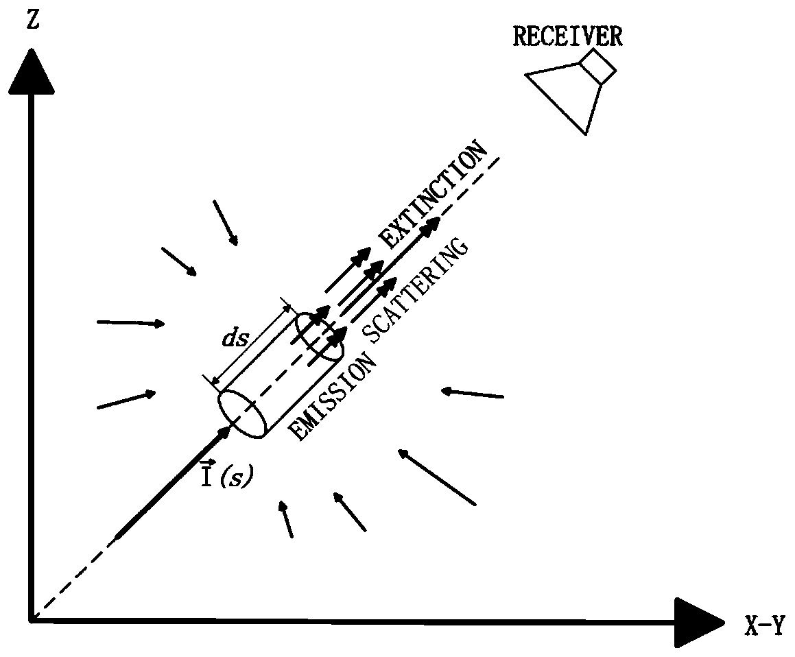
[0063] S1: Obtain the observed radiation amount of an observation area of ​​the microwave imager in an observation time period, and at the same time, calculate the simulated radiation amount of the observation area of ​​the microwave imager in the observation time period according to the radiation transfer model;

[0064] S2: According to the observed radiation amount and the simulated radiation amount, the single deviation value of the rising orbit of the microwave imager in the case of ascending orbit and the single deviation value of the descending orbit of the microwave imager in the case of descending orbit are calculated respectively;

[0065] S3: According to the single deviation value of the ascending rail and the single deviation value of the descending rail, calculate the double deviation va...

Embodiment 2

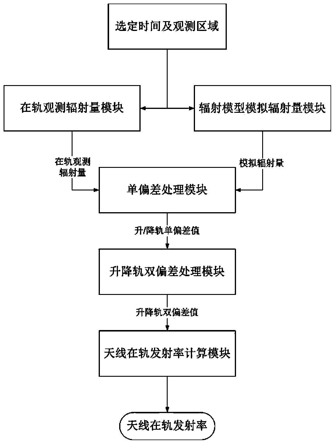
[0127] see figure 2 , this embodiment provides a device for calibrating the on-orbit emissivity of the spaceborne microwave imager antenna based on Embodiment 1,

[0128] The on-orbit observation radiation module is configured to obtain the observation radiation of an observation area of ​​the microwave imager in an observation time period;

[0129] The radiation model simulation radiation amount module is configured to calculate the simulated radiation amount of the observation area of ​​the microwave imager during the observation time period according to the radiation transfer model;

[0130] The single deviation processing module is configured to calculate and obtain the orbit single deviation value of the microwave imager when the orbit is ascending and the orbit single deviation value of the microwave imager when the orbit is descending according to the observed radiation amount and the simulated radiation amount;

[0131] The ascending rail double deviation processing ...


PUM


Abstract

The invention discloses a calibration method and device for on-orbit emissivity of a satellite-borne microwave imager antenna. The method comprises the following steps of S1, acquiring observation radiation quantity of an observation region of a microwave imager within an observation time frame, and simultaneously calculating to obtain simulation radiation quantity of the observation region of themicrowave imager within the observation time frame by a radiation transmission model; S2, respectively calculating to obtain ascending single deviation and descending single deviation according to the observation radiation quantity and the simulation radiation quantity; S3, calculating to obtain ascending and descending dual deviation according to the ascending single deviation and the descendingsingle deviation; and S4, calculating physical temperature difference of the antenna according to a physical temperature of the antenna under condition of ascending and descending, and calculating toobtain the on-obit emissivity of the antenna according to the ascending and descending dual deviation and the physical temperature difference so that calibration of the on-orbit emissivity of the microwave imager antenna is realized. The method has the technical characteristics of accurate calculation of the on-obit emissivity of the antenna, simplicity and high efficiency.

Description

technical field [0001] The invention belongs to the technical field of aerospace remote sensing, and in particular relates to a method and a device for calibrating the on-orbit emissivity of a satellite-borne microwave imager antenna. Background technique [0002] By measuring surface and atmospheric radiation information, microwave imagers can retrieve parameters such as temperature, wind speed, sea ice, snow cover, soil moisture, and precipitation, and are widely used in the detection of atmosphere, ocean, and land environments. Whether the microwave imager can obtain accurate and effective surface brightness temperature remote sensing data when it is in orbit mainly depends on the calibration accuracy of the microwave imager. Therefore, in order to obtain accurate and effective remote sensing data of surface brightness temperature, it is necessary to greatly improve the calibration accuracy of the microwave imager. [0003] In the process of traditional calibration, the ...

Claims


Application Information

Patent Timeline
Patent Type & Authority Applications(China)
IPC IPC(8): G01S7/40G01S13/89
CPCG01S7/4008G01S13/89
Inventor 谢鑫新孟婉婷李雪李恩晨王平凯董克松
Owner SHANGHAI SPACEFLIGHT INST OF TT&C & TELECOMM
Learn More