Large-capacity condensation heat exchange device
A condensing heat exchange and large-capacity technology, which is applied to heat exchanger shells, steam/steam condensers, heat exchange equipment, etc., can solve problems such as welding leakage hazards and heavy welding workload
- Summary
- Abstract
- Description
- Claims
- Application Information
AI Technical Summary
Problems solved by technology
Method used
Image
Examples
Embodiment 1
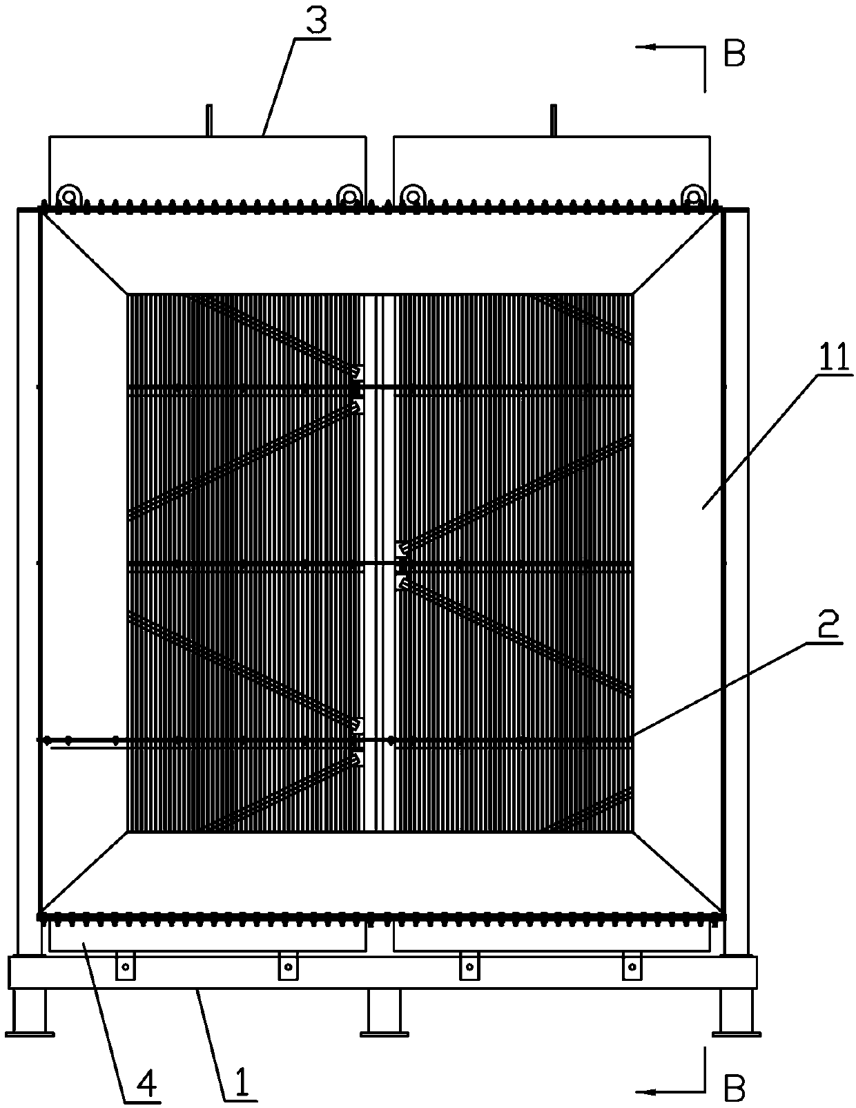
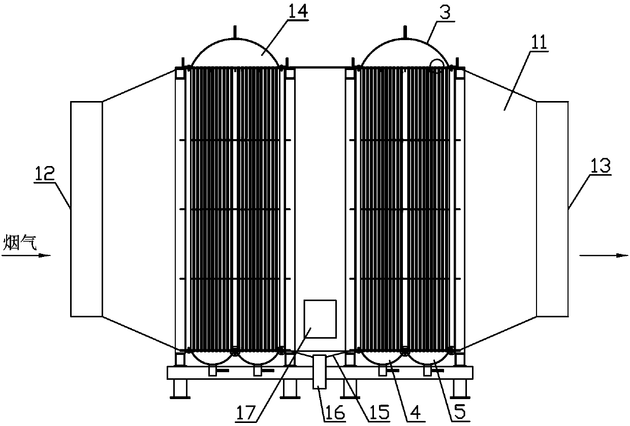
[0055] For convenience of description and better understanding, this embodiment will figure 2 The left side shown in the direction is defined as "left", the figure 2 The right side shown in the direction is defined as "Right", the figure 2 The upper side shown in the direction is defined as "upper", the figure 2 The lower side shown in the direction is defined as "lower", and the terms "left", "left side", "right", "right side", "upper", "lower", "upper end", "lower end" referred to in this application "are all based on figure 2 Orientation shall prevail. Will figure 1 The left and right direction shown in the direction is defined as the "front and back" direction, and the "front and back" mentioned in this application are all referred to as figure 1 Orientation shall prevail.
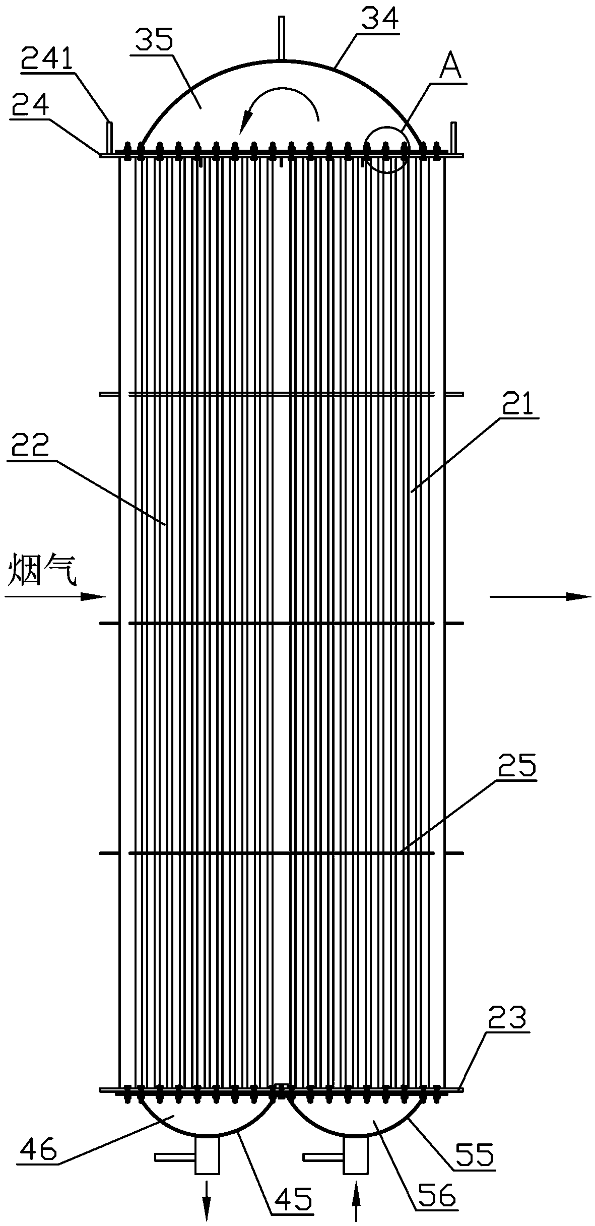
[0056] Such as figure 1 with figure 2 As shown, a large-capacity condensation heat exchange device described in this embodiment includes: a main frame 1 and a smoke box body 11 arranged o...
Embodiment 2
[0069] In Embodiment 1, between the large header flange 32 and the upper side plate 24, between the outlet header flange 42 and the left half of the lower side plate 23, between the water inlet header flange 52 and the right half of the lower side plate 23 As long as they can be sealed and connected, the specific flange sealing structure is not limited. However, the common flange sealing structure on the market can only be used in working conditions with low working pressure, and leakage problems will inevitably occur during use. In view of the above-mentioned problems in the common flange sealing structure in the market, this embodiment optimizes the flange sealing structure on the basis of Embodiment 1, and the specific structure is as follows:
[0070] Such as Figure 10 with Figure 11As shown, a first sealing structure is provided between the large header flange 32 and the upper side plate 24, and the first sealing structure is: the sealing surface of the large header f...
Embodiment 3
[0082] In Embodiment 1, between the large header flange 32 and the upper side plate 24, between the outlet header flange 42 and the left half of the lower side plate 23, between the water inlet header flange 52 and the right half of the lower side plate 23 As long as they can be sealed and connected, the specific flange sealing structure is not limited. However, the common flange sealing structure on the market can only be used in working conditions with low working pressure, and leakage problems will inevitably occur during use. In view of the above-mentioned problems in the common flange sealing structure in the market, this embodiment optimizes the flange sealing structure on the basis of Embodiment 1, and the specific structure is as follows:
[0083] see Figure 12 with Figure 14 As shown in the structure, the first sealing structure is as follows: a first retaining ring is arranged on the sealing surface of the large header flange 32, and the first main sealing strip ...
PUM
 Abstract
Description
Claims
Application Information
 - R&D Engineer
- R&D Manager
- IP Professional
- Industry Leading Data Capabilities
- Powerful AI technology
- Patent DNA Extraction
Browse by: Latest US Patents, China's latest patents, Technical Efficacy Thesaurus, Application Domain, Technology Topic, Popular Technical Reports.
© 2024 PatSnap. All rights reserved.Legal|Privacy policy|Modern Slavery Act Transparency Statement|Sitemap|About US| Contact US: help@patsnap.com


