
Energy storage device

A technology for energy storage devices and installation chambers, applied to electrical components, electrochemical generators, circuits, etc., can solve the problems of long time consumption and complicated operation, and achieve the effect of short time consumption and simple operation

Active Publication Date: 2019-08-23
HENAN PINGGAO ELECTRIC +2
View PDF16 Cites 2 Cited by
  • Summary
  • Abstract
  • Description
  • Claims
  • Application Information

AI Technical Summary

Problems solved by technology

[0005] The object of the present invention is to provide an energy storage device to solve the problem of complex operation and long time consumption when accessing the battery box of the energy storage device in the prior art

Method used


Image

  • Energy storage device
  • Energy storage device
  • Energy storage device

Examples


Embodiment Construction

[0033] Embodiments of the present invention will be further described below in conjunction with the accompanying drawings.

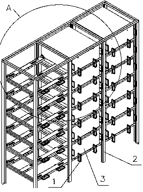
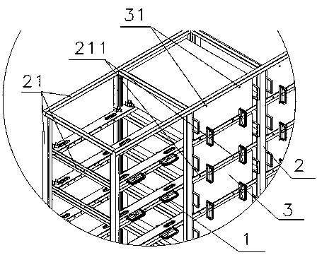
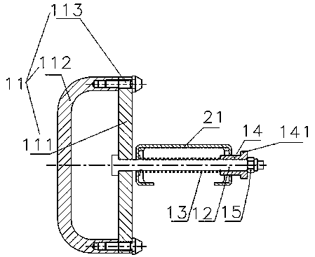
[0034] A specific embodiment of the energy storage device of the present invention is a portable and fixed mobile energy storage container, such as figure 1 and figure 2 As shown, the mobile energy storage container includes a battery rack 2 and a battery box 3 installed in the battery rack 2; the battery rack 2 is arranged in three rows along the left and right directions, and the battery rack 2 has a battery box installation cavity for the battery box 3 to be loaded and unloaded in a push-pull manner , The battery box installation cavity is surrounded by support beams 21. The supporting beam 21 located at the front of the battery installation cavity surrounds the battery loading and unloading opening for loading and unloading the battery box 3 , and the supporting beam 21 extends along the lengthwise direction. Such as image 3 As shown, the energy...


PUM


Abstract

The invention relates to an energy storage device. The energy storage device comprises a battery rack and a battery box mounted in the battery rack, and the battery rack comprises a battery box mounting cavity. The energy storage device further comprises a handle mechanism, and the handle mechanism comprises a handle, a rotating shaft and an elastic reset piece, wherein the rotating shaft is provided with an axis parallel to the push-pull direction of the battery box, and the handle is provided with a stop arm, and has a stop position and an avoidance position. The elastic reset piece is usedfor applying an acting force moving towards the battery box loading direction to the handle, and the handle is further provided with a positioning part. The opening edges of the battery box and the battery box mounting cavity are provided with corresponding positioning adaptive parts. When the energy storage device is used for storing and taking the battery box, the operation is easy, and the consumed time is short. When an emergency occurs, the battery box loading and unloading path can be rapidly opened to treat the battery box, and the potential safety hazards are rapidly eliminated.

Description

technical field [0001] The invention relates to an energy storage device. Background technique [0002] As an important way of electric energy storage, battery energy storage has the advantages of flexible configuration of power and energy and fast response speed, which makes battery energy storage an irreplaceable position in cooperating with centralized or distributed new energy grid connection and grid operation assistance. [0003] Batteries and auxiliary equipment for storing electrical energy are often carried by mobile energy storage containers to be transported to places where electrical energy is needed. The Chinese invention patent application with application publication number CN105129269A and application publication date of December 09, 2015 discloses an energy storage battery cabinet. The mounting hole on the front of the rack is used to locate the battery box and prevent the battery box from coming out of the battery rack from the front of the battery rack. ...

Claims


Application Information

Patent Timeline
IPC IPC(8): H01M2/10H01M10/42
CPCH01M10/4207H01M50/20H01M50/256Y02E60/10
Inventor 李娟田刚领张柳丽罗军牛哲荟王红涛王路平李占军杨文辉仝晓武
Owner HENAN PINGGAO ELECTRIC
Learn More