
Light incidence structure of backlight module, and backlight module

A backlight module and technology on the back, applied in light guides, optics, optical components, etc., can solve problems such as Hotspot phenomenon on the light incident side, light off, affecting product reliability, etc.

Inactive Publication Date: 2019-08-23
创维光电科技(深圳)有限公司
View PDF5 Cites 2 Cited by
  • Summary
  • Abstract
  • Description
  • Claims
  • Application Information

AI Technical Summary

Problems solved by technology

In order to make the brightness of the backlight module reach a higher standard, but due to the low light efficiency of the light guide plate and the need for a narrow frame of the backlight module, we usually increase the number and power of LEDs
[0004] For the side-type backlight module structure, increasing the power and number of LEDs will lead to too small spacing between LEDs, which will cause LEDs to turn off due to insufficient heat dissipation, which will affect product reliability.
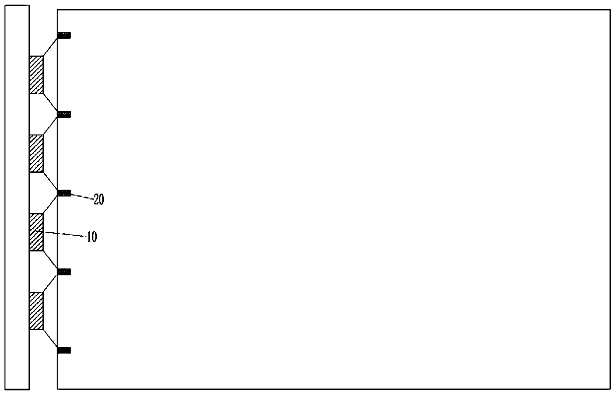
However if figure 1 As shown, when the number of LED10 is not enough, it will lead to the Hotspot phenomenon on the light incident side, such as figure 1 Dark Zone 20 shown

Method used


Image

  • Light incidence structure of backlight module, and backlight module
  • Light incidence structure of backlight module, and backlight module
  • Light incidence structure of backlight module, and backlight module

Examples


Embodiment Construction

[0032] In order to make the purpose, technical solutions and advantages of the embodiments of the present invention clearer, the technical solutions in the embodiments of the present invention will be clearly and completely described below in conjunction with the drawings in the embodiments of the present invention. Obviously, the described embodiments It is a part of embodiments of the present invention, but not all embodiments. The components of the embodiments of the invention generally described and illustrated in the figures herein may be arranged and designed in a variety of different configurations.

[0033] Accordingly, the following detailed description of the embodiments of the invention provided in the accompanying drawings is not intended to limit the scope of the claimed invention, but merely represents selected embodiments of the invention. Based on the embodiments of the present invention, all other embodiments obtained by persons of ordinary skill in the art wi...


PUM


Abstract

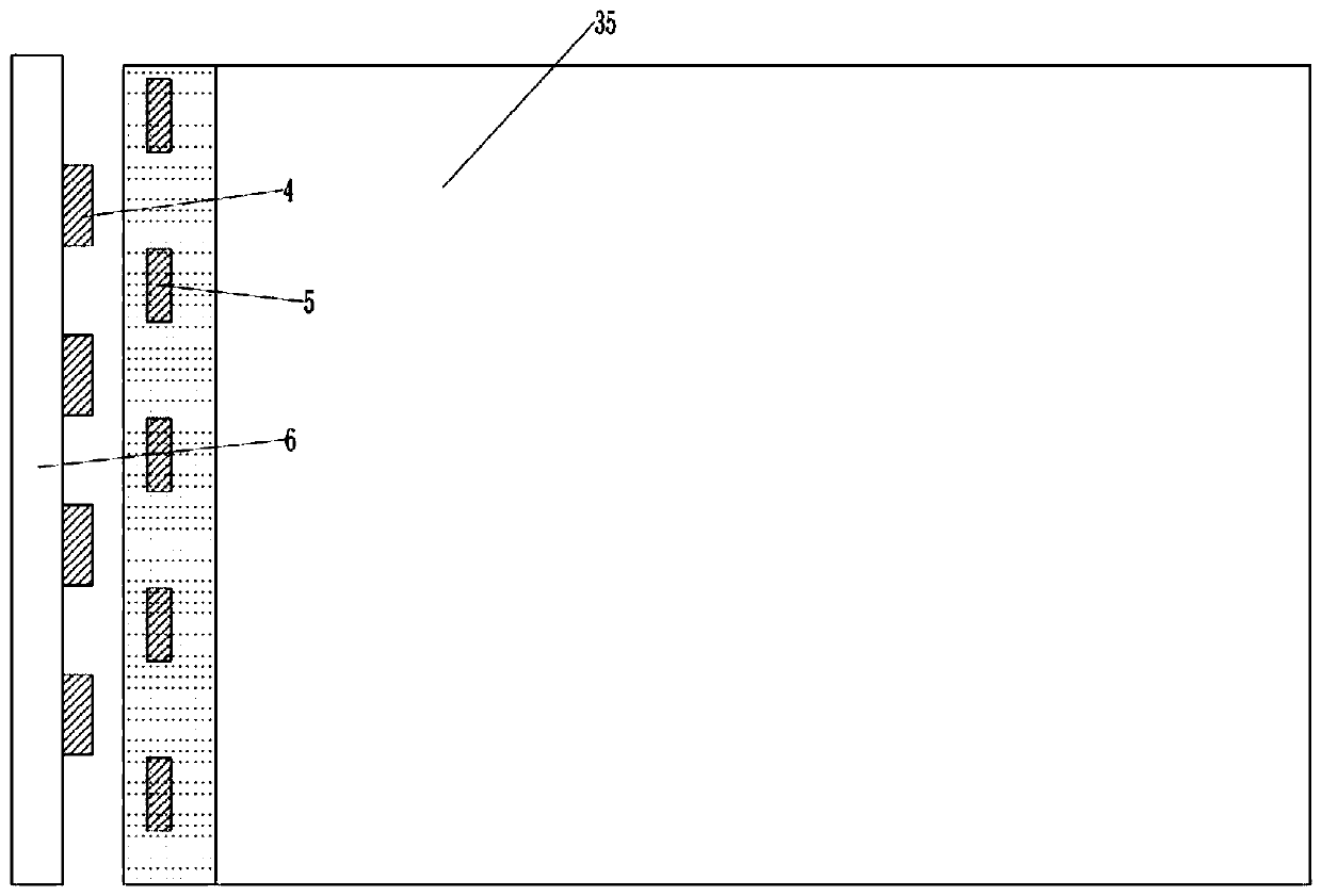
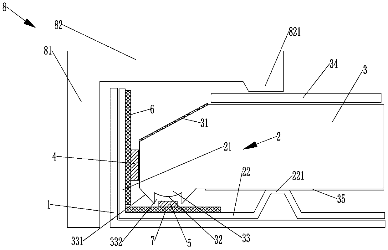
The invention relates to the technical field of backlight modules, and discloses a light incidence structure of a backlight module. The structure comprises a metal backplane, a heat dissipation bar, alight guiding plate, first LEDs (Light Emitting Diode) and second LEDs, wherein the heat dissipation bar comprises a first side plate and a second side plate, and the first side plate and the secondside plate are mutually vertical; the first side plate is fixed on the side edge of the metal backplane, and the second side plate is positioned on the back side of the light guiding plate; the innerside of the first side plate is provided with a plurality of first LEDs which are evenly distributed along a length direction, and the first LEDs just face the side light incidence surface of the light guiding plate; the inner side of the second side plate is provided with a plurality of second LEDs which are evenly distributed along a length direction; the first LEDs and the second LEDs are in staggered arraignment; the front side corner of the light guiding plate is chamfered; a chamfering inclination surface is provided with a side reflection sheet; rays emitted from the second LEDs can beirradiated to the side reflection sheet; and the side reflection sheet is configured into a way that the rays emitted from the second LEDs are refracted into the light guiding plate. The backlight module comprises the above light incidence structure of the backlight module, can meet luminance requirements and also can effectively carry out heat dissipation.

Description

technical field [0001] The invention relates to the technical field of backlight modules, in particular to a light incident structure of the backlight module and the backlight module. Background technique [0002] In the liquid crystal display device, the backlight module is one of the key components of the liquid crystal display device, which is mainly used to provide sufficient brightness and uniformly distributed light source so that the liquid crystal panel can display images normally. [0003] Generally, the LED backlight in the backlight module is divided into direct-type backlight module and side-type backlight module. As consumers continue to improve the quality and appearance of displays, the requirements for backlight modules are also getting higher and higher. . The side-type backlight module can convert the line light source into a surface light source through the light guide plate to achieve a thinner display. Usually, in order to meet the display quality requ...

Claims


Application Information

Patent Timeline
IPC IPC(8): G02F1/13357G02B6/00
CPCG02B6/002G02B6/0031G02B6/0055G02B6/0065G02B6/0073G02B6/0083G02B6/0085G02B6/009G02F1/133603G02F1/133605G02F1/133608G02F1/133628
Inventor 韩继远孟长军
Owner 创维光电科技(深圳)有限公司
Learn More