
A virtual reality display device and driving method thereof

A display device and virtual reality technology, which is applied in the direction of instruments, optics, optical components, etc., can solve the problems that the display area cannot be enlarged, the sense of immersion is poor, and the viewing angle is small, so as to achieve excellent visual display effect and eliminate the effect of screen door effect

Active Publication Date: 2021-06-04
SEEYA OPTRONICS LTD
View PDF5 Cites 0 Cited by
  • Summary
  • Abstract
  • Description
  • Claims
  • Application Information

AI Technical Summary

Problems solved by technology

If the resolution is increased, because the display area cannot be enlarged, the viewing angle will be less, and the sense of immersion will be poor.

Method used


Image

  • A virtual reality display device and driving method thereof
  • A virtual reality display device and driving method thereof
  • A virtual reality display device and driving method thereof

Examples


Embodiment 1

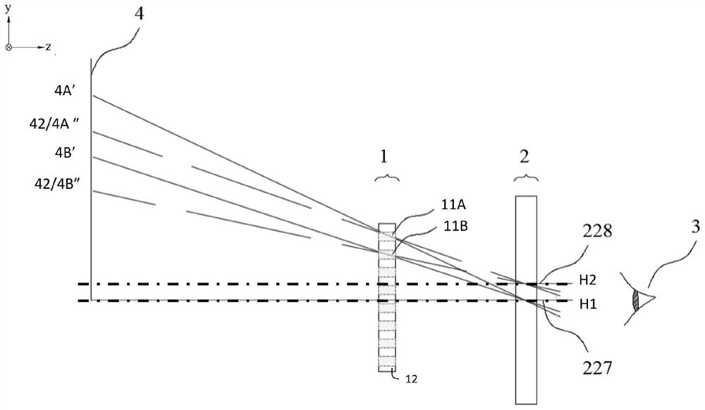
[0028] Please refer to figure 1 and figure 2 , figure 1 It is a schematic diagram of a virtual reality display device provided in Embodiment 1 of the present invention, figure 2 for figure 1 Schematic diagram of the working of the shown virtual reality display device. Such as figure 1 As shown, the virtual reality display device includes a display device 1 and a lens system 2 arranged on the Z axis, the display device 1 includes a plurality of pixel units 11 arranged in a matrix on the X axis and the Y axis, and the lens system 2 has multiple A plurality of different optical axes in a time period, in a plurality of time periods, through the different optical axes, a plurality of pixel units 11 respectively form a plurality of pixel virtual images 4, and the human eye 3 observes the display device 1 through the lens system 2, which can The magnified virtual image 4 formed by the display device 1 is seen.

[0029] The virtual reality display device provided by the presen...

Embodiment 2

[0038] Please refer to image 3 , is a schematic diagram of the lens system provided by Embodiment 2 of the present invention, please refer to figure 1 and image 3 , as shown in the figure, the lens system 2 includes a liquid crystal lens 221, by changing the liquid crystal refractive index distribution of the liquid crystal lens 221, a plurality of different optical axes are formed.

[0039] The liquid crystal lens 221 includes a plurality of pixel units, and each pixel unit includes a first electrode 223 arranged on the inner side of the first substrate 222 and a second electrode 225 arranged on the inner side of the second substrate 226. image 3 In the shown structure, the first electrode 223 is a common electrode, the second electrode 225 is a pixel electrode, the pixel electrodes 225 of each pixel unit of the liquid crystal lens are independent from each other, and the common electrodes 223 of each pixel unit are connected together. A liquid crystal layer 224 is dispo...


PUM


Abstract

The present invention provides a virtual reality display device, including a display device and a lens system. The display device includes a plurality of pixel units, and the lens system has a plurality of different optical axes in different time periods; Each pixel unit forms a plurality of pixel virtual images, and the present invention also provides a driving method for the above-mentioned virtual reality display device. In the virtual reality display device and driving method provided by the present invention, by setting the optical axes at different positions of the lens system in multiple time periods, each pixel unit of the display device can generate different pixel virtual images in different time periods. When the time period is quickly switched, a visual effect with a multiple increase in resolution is formed.

Description

technical field [0001] The invention relates to the field of display technology, in particular to a virtual reality display device capable of improving resolution and a driving method thereof. Background technique [0002] VR (Virtual Reality, virtual reality) display was proposed in the 1980s. It integrates computer graphics technology, computer simulation technology, sensor technology, display technology and other science and technology. It creates a virtual information environment in the multi-dimensional information space. It can enable users to have an immersive sense of immersion, have a perfect interaction ability with the environment, and help to inspire ideas. A virtual reality display device in the prior art generally includes a computer processing system, an image processing system, a display panel, and an optical system. Among them, the computer processing system captures the character's behavior and the external environment through external sensors, and then pr...

Claims


Application Information

Patent Timeline
Patent Type & Authority Patents(China)
IPC IPC(8): G02B27/01G02F1/13
CPCG02B27/0101G02B2027/0147G02F1/1313
Inventor 刘鹭牛磊夏婉婉
Owner SEEYA OPTRONICS LTD
Learn More