
A dynamic simulation test method for a power system

A dynamic simulation test and power system technology, which is applied in engine testing, machine/structural component testing, instruments, etc., can solve the problem of simulating the total temperature change of the incoming flow for a long time, simulating the total pressure change of the incoming flow for a short time, Problems such as high experimental costs, to achieve the effect of authentic test results, reduced costs, and reduced manufacturing

Active Publication Date: 2020-12-25
BEIJING RES INST OF MECHANICAL & ELECTRICAL TECH
View PDF17 Cites 0 Cited by
  • Summary
  • Abstract
  • Description
  • Claims
  • Application Information

AI Technical Summary

Problems solved by technology

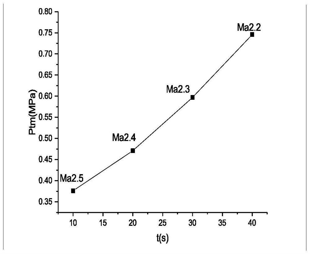
[0003] The general working process of the direct connection test bench is to adjust the simulated gas path parameters to reach a certain flight state, that is, to reach a certain Mach number, altitude and angle of attack state, and the engine is ignited. In the process, generally only the fuel flow supplied to the engine is adjusted. In order to obtain the combustion performance of the engine in a fixed state, but one test can only obtain the performance of one state, the test efficiency is low, and one test needs to design a throat, and the test cost is high; There are problems such as matching, followability and stability of the temperature. The time for the test bench to simulate the change of the total temperature of the incoming flow is relatively long, and the time for simulating the change of the total pressure of the incoming flow is short. During the experiment process of adjusting the temperature and pressure at the same time, it will cause difficulties. increase in time, wasted time and increased costs

Method used


Image

  • A dynamic simulation test method for a power system
  • A dynamic simulation test method for a power system
  • A dynamic simulation test method for a power system

Examples


Embodiment Construction

[0030] The present invention will be described in detail below in conjunction with specific examples and accompanying drawings.

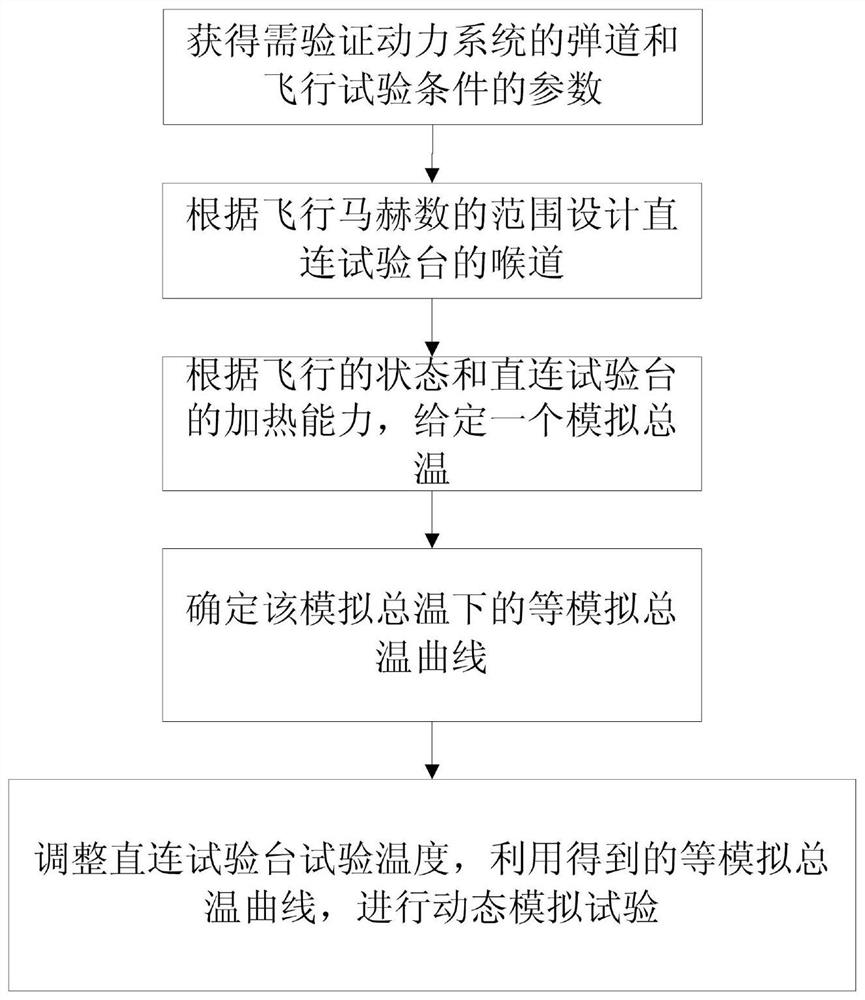
[0031] Such as figure 1 Shown, the technical solution of the present invention: a kind of power system dynamic simulation test method, the steps are as follows,

[0032] Step 1. Obtain the parameters required to verify the ballistic and flight test conditions of the power system, including flight Mach number, flight altitude and ambient static temperature under local flight conditions;

[0033] Among them, the ballistic trajectory needs to be verified. The flight Mach number and flight altitude can be obtained from the trajectory, and the static temperature of the environment under local flight conditions can be measured.

[0034] Step 2. Design the throat directly connected to the test bench according to the range of flight Mach number;

[0035] The throat design steps are:

[0036] S1. Verify the flight Mach number range of the ballistic trajec...


PUM


Abstract

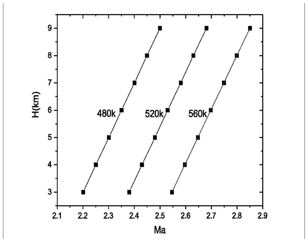
The invention provides a dynamic simulation test method for a power system. Step 1, parameters of a trajectory of the power system to be verified and flight test conditions are obtained; step 2, a throat of a direct connection test bed is designed according to a range of flight Mach numbers; step 3, a simulated total temperature Ttm is given according to a state of flight and heating capacity of the direct connection test bed; step 4, an iso-simulated total temperature curve under the simulated total temperature Ttm is determined according to the determined simulated total temperature Ttm anda simulated total temperature formula; and step 5, according to the determined total temperature Ttm, test temperature of the direct connection test bed is adjusted, and the obtained iso-simulated total temperature curve is used to carry out a dynamic simulation test. The dynamic simulation test method for a power system of the invention can quantitatively simulate a flight process of an aircraftand evaluate dynamic working characteristics of an engine system, simplifies steps of the direct connection test bed during the test, shortens a test period, and reduces the test cost.

Description

technical field [0001] The invention relates to a dynamic simulation test method of a power system, which belongs to the technical field of engine power system tests. Background technique [0002] The power system is an important part of a supersonic flight missile, and its development and final state determination often require hundreds of ground tests. There are three main methods of power system ground test: wind tunnel test bench, free jet bench, direct connection test bench. The direct connection test is still one of the most important means in the ground test research of the ramjet engine. The engine is connected to the gas circuit of the test bench through a test section. Through the detailed design of the contraction and expansion section of the measurement section, the simulated total pressure, total temperature and oxygen content of the equipment are adjusted to simulate the actual air flow through the combustion chamber. Uses include: (1) Study the ignition and ...

Claims


Application Information

Patent Timeline
Patent Type & Authority Patents(China)
IPC IPC(8): G01M15/00
CPCG01M15/00
Inventor 周硕郭敬涛杜军
Owner BEIJING RES INST OF MECHANICAL & ELECTRICAL TECH
Learn More