
A reversing valve and reversing method for controlling on-off of microfluidic pipeline

A technology of microfluidic control and reversing valve, which is applied in the direction of valve details, valve device, valve operation/release device, etc. It can solve the problems of limited size, large volume, high cost of electromagnetic reversing valve, etc., and achieve manufacturing cost Reduce, reduce the effect of limit size

Active Publication Date: 2020-05-29
SOUTHEAST UNIV
View PDF5 Cites 0 Cited by
  • Summary
  • Abstract
  • Description
  • Claims
  • Application Information

AI Technical Summary

Problems solved by technology

When using a manual valve, the operator can only manually control the simple liquid circuit. Although the electromagnetic reversing valve can work automatically, it is relatively large in size. Very limited, even impossible to use with existing directional valves
The use cost of the existing electromagnetic reversing valve is also high, so how to reduce the size of the reversing valve on the basis of solving the automatic reversing control, reduce the manufacturing cost, and make the reversing valve used in a wider range of technologies particularly important in the field

Method used


Image

  • A reversing valve and reversing method for controlling on-off of microfluidic pipeline
  • A reversing valve and reversing method for controlling on-off of microfluidic pipeline
  • A reversing valve and reversing method for controlling on-off of microfluidic pipeline

Examples


Embodiment Construction

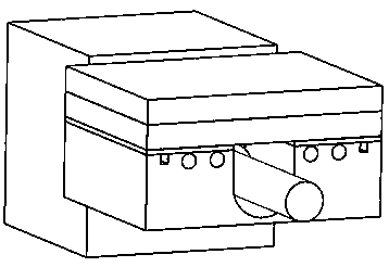
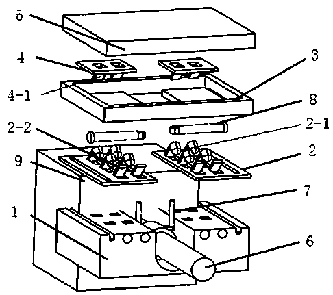
[0029] figure 1 As shown, a push type reversing valve for controlling multi-pipe reversing of the present invention consists of a reversing valve housing part, a cover part, a push rod, an internal splint, a shrapnel plate, a ramp plate, a motor box and a screw rod Stepper motor composition:

[0030] figure 2 As shown, the horizontal push rod is assembled with the vertical push rod. The horizontal push rod moves inward and outward along the rails on both sides of the shrapnel plate by means of the screw screw. After passing through the shrapnel in the shrapnel state on the shrapnel board, the horizontal push rod presses down the shrapnel. , so the shrapnel enters the hole located on the top of the shell below. The position of the hole is the channel through which the pipeline in the shell passes. The downward pressure of the shrapnel makes the pipeline blocked, and the pipeline is unblocked at the position without the shrapnel, forming a combination of pipeline on-off. , Th...


PUM


Abstract

The invention discloses a reversing valve for controlling on-off of a microfluidic pipeline and a reversing method thereof. The reversing valve comprises a pair of vertical push rods, and the verticalpush rods are pushed by a screw stepping motor. Mounting holes are formed in the top end of a transverse push rod, and are used for matching with the vertical push rods. An elastic sheet plate is arranged on the upper part of the shell through which the pipeline passes; elastic sheets with different combinations are arranged at different positions of the shell; different closure results of the pipeline are generated in a pressing mode; tail parts of the elastic sheets are fixedly connected with the elastic sheet plate, and are in an elastic opening state in a natural state; a clamping plate is arranged above the elastic sheet plate, and grooves are formed on two sides of the elastic sheet plate and the clamping plate to serve as tracks for movement of the transverse push rod; the transverse push rod defines the position and the movement direction through a track of the clamping plate and the matching with the vertical push rods; slopes are arranged at the initial positions and the stop positions of the movements to achieve return strokes of the push rods; and time of clockwise and counterclockwise movements of the screw stepping motor determines on-off time of the pipeline.

Description

technical field [0001] The invention relates to the field of pipeline reversing valves, in particular to a microfluidic pipeline reversing valve and a reversing method thereof. Background technique [0002] The existing pipeline reversing valves are mainly divided into two types: on-off manual valves and electromagnetic reversing valves. Although the two types of reversing valves have various forms, they basically control the flow direction or flow of liquid in two to three pipelines. broken. When using a manual valve, the operator can only control the simple liquid circuit manually. Although the electromagnetic reversing valve can work automatically, it is relatively large in size. Very limited, even the existing directional valve cannot be used. The use cost of the existing electromagnetic reversing valve is also high, so how to reduce the size of the reversing valve on the basis of solving the automatic reversing control, reduce the cost of manufacturing, and make the r...

Claims


Application Information

Patent Timeline
Patent Type & Authority Patents(China)
IPC IPC(8): F16K31/04F16K31/44
CPCF16K31/04F16K31/44
Inventor 张乐张赤斌
Owner SOUTHEAST UNIV
Learn More