
Turbine bypass control system

A steam turbine bypass and control system technology, applied in steam engine installations, mechanical equipment, engine components, etc., can solve the problems of easy error, low degree of automation, inconvenient use, etc., to reduce the error rate, realize centralized monitoring, and realize automatic running effect

Active Publication Date: 2019-08-23
南海发电一厂有限公司
View PDF19 Cites 3 Cited by
  • Summary
  • Abstract
  • Description
  • Claims
  • Application Information

AI Technical Summary

Problems solved by technology

[0003] The automation degree of the existing steam turbine bypass control system is not high, and manual operation of each control valve is often required, which is inconvenient to use and error-prone

Method used


Image

  • Turbine bypass control system
  • Turbine bypass control system
  • Turbine bypass control system

Examples


Embodiment Construction

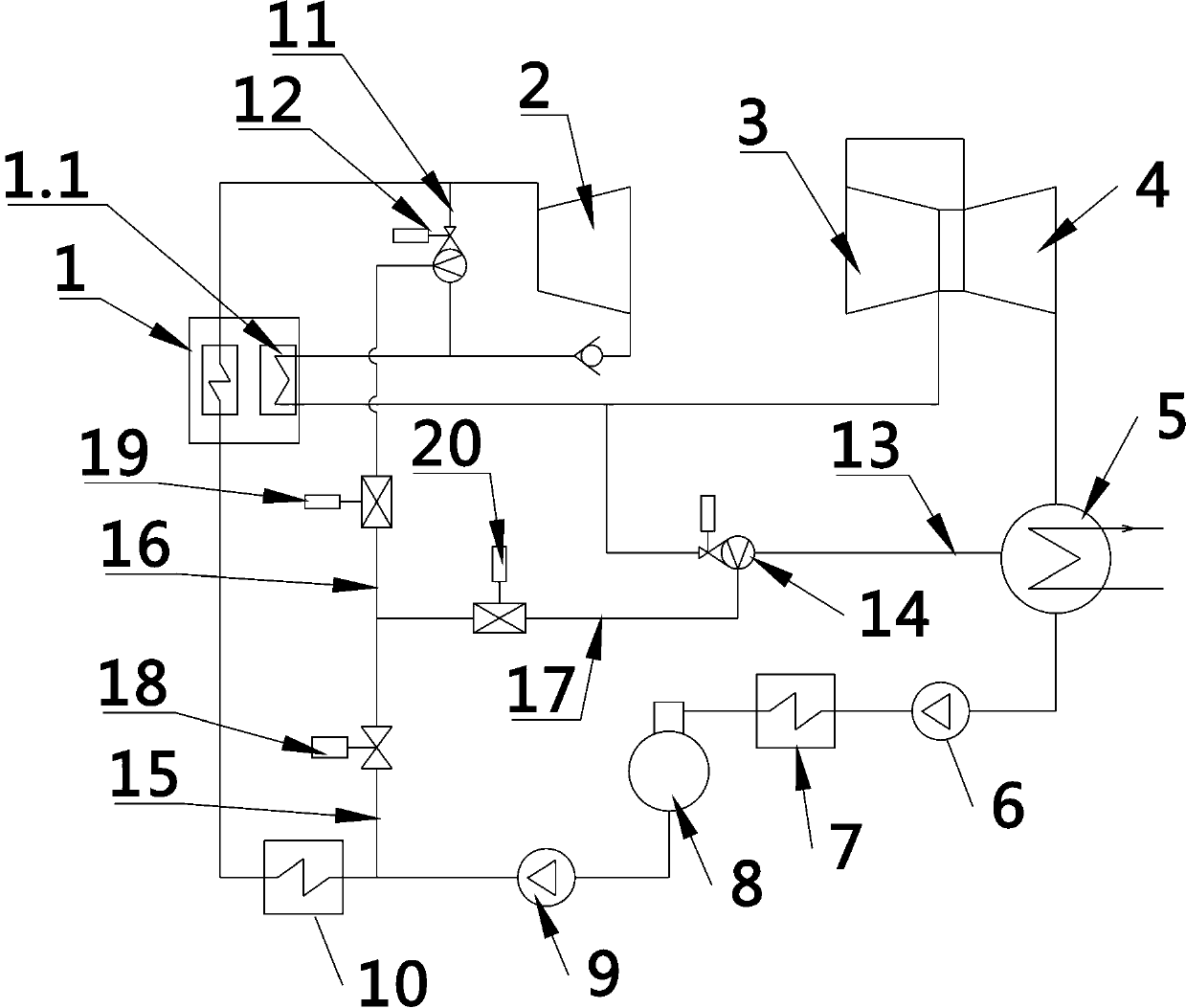
[0023] The present invention provides a steam turbine bypass control system. In order to make the purpose, technical solution and effect of the present invention clearer and clearer, the present invention will be further described in detail below with reference to the accompanying drawings and examples. It should be understood that the specific embodiments described here are only used to explain the present invention, not to limit the present invention.

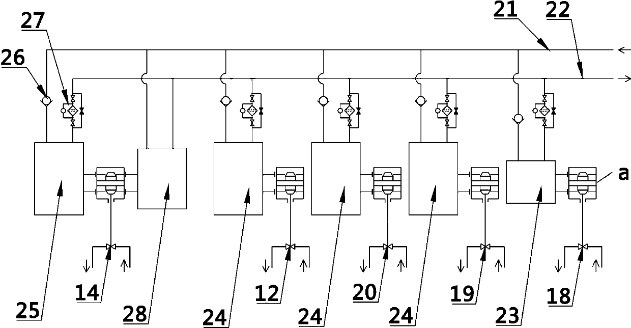
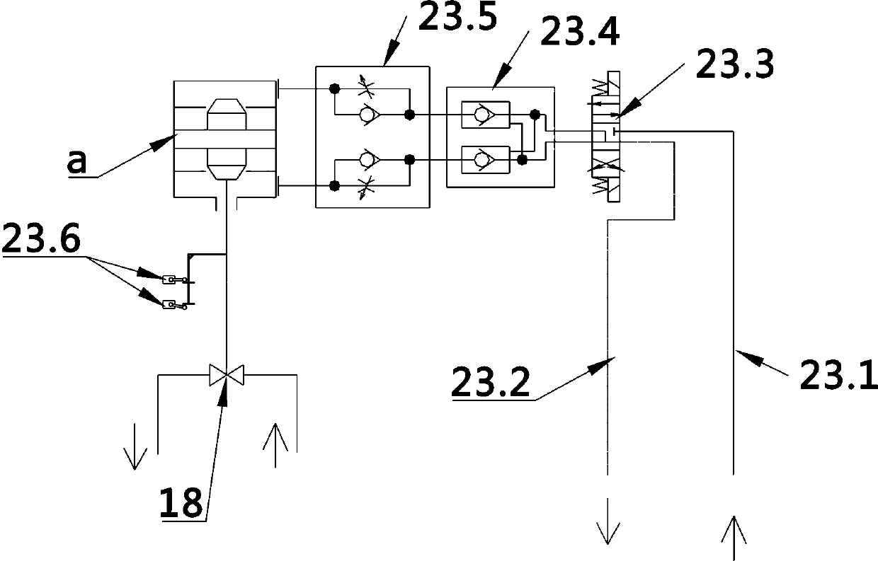
[0024] see Figure 1-5 , a steam turbine bypass control system provided by the present invention includes boiler 1, high-pressure cylinder 2, medium-pressure cylinder 3, low-pressure cylinder 4, condenser 5, condensate pump 6, low-pressure heater 7, Oxygenator 8, feed water pump 9, and high-pressure heater 10; the outlet of high-pressure cylinder 2 is connected to the inlet of boiler reheater 1.1 through pipelines, and the outlet of reheater 1.1 is connected to the inlet of medium-pressure cylinder 3 through pipelines; The i...


PUM


Abstract

The invention provides a turbine bypass control system comprising a boiler, a high-pressure cylinder, a medium-pressure cylinder, a low-pressure cylinder, a condenser, a condensate pump, a low-pressure heater, a deaerator, a feed water pump, a high-pressure heater, a high-pressure bypass, a high-pressure bypass pressure reducing valve, a low-pressure bypass, a low-pressure bypass pressure reducingvalve, a first water supply pipe, a second water supply pipe, a third water supply pipe, a desuperheating water shutoff valve, a high-pressure bypass desuperheating water valve and a low-pressure bypass desuperheating water valve. The turbine bypass control system further comprises a valve control system used for controlling the high-pressure bypass pressure reducing valve, the low-pressure bypass pressure reducing valve, the desuperheating water shutoff valve, a high-pressure bypass desuperheating water valve and a low-pressure bypass desuperheating water valve to work and an upper computer.The valve control system is electrically connected with the upper computer. The turbine bypass control system is high in automation degree.

Description

technical field [0001] The invention relates to the technical field of steam turbine control, in particular to a steam turbine bypass control system. Background technique [0002] The thermal power generation unit converts water into high-pressure steam through the boiler, and then sends the high-pressure steam to the high-pressure cylinder, medium-pressure cylinder and low-pressure cylinder of the steam turbine to drive the steam turbine to rotate and generate electricity. When the unit is started and the load is shed, the steam will be partially or completely led to the condenser through the bypass system, thereby reducing the steam pressure entering the high-pressure cylinder, medium-pressure cylinder and low-pressure cylinder to shorten the start-up time, and It can ensure that the boiler is in a hot standby state when the load is shed, so that it can be started quickly again. [0003] The automation degree of the existing steam turbine bypass control system is not high...

Claims


Application Information

Patent Timeline
IPC IPC(8): F01D17/10F01K11/02
CPCF01D17/10F01K11/02
Inventor 孙明亮张擎
Owner 南海发电一厂有限公司
Learn More