
A method for improving the recovery of natural gas hydrate reservoirs through artificial tight cap rocks

A hydrate and natural gas technology, applied in the fields of fluid production, earthwork drilling, sealing/seal, etc., can solve problems such as restricting the development and utilization of natural gas hydrate reservoirs, affecting the development of natural gas hydrate reservoirs, and limiting the rate of hydrate decomposition. Achieve the effect of simple structure, increase pressure difference and prevent reservoir collapse

Active Publication Date: 2021-07-23
CHINA UNIV OF PETROLEUM (EAST CHINA)
View PDF0 Cites 1 Cited by
  • Summary
  • Abstract
  • Description
  • Claims
  • Application Information

AI Technical Summary

Problems solved by technology

When the depressurization is performed, the seawater enters the bottom of the well through the permeable caprock, causing a large amount of ineffective water production in the production well, and an effective pressure difference cannot be formed between the reservoir and the production well, thereby limiting the decomposition rate of hydrate; Methane gas may migrate upwards into the atmosphere along the permeable cover, exacerbating the greenhouse effect
Therefore, the permeability of the caprock significantly affects the development of gas hydrate reservoirs. However, there is no effective method for exploiting gas hydrate reservoirs with permeable caprocks, which largely restricts the development of such gas hydrate reservoirs. develop and use

Method used


Image

  • A method for improving the recovery of natural gas hydrate reservoirs through artificial tight cap rocks
  • A method for improving the recovery of natural gas hydrate reservoirs through artificial tight cap rocks
  • A method for improving the recovery of natural gas hydrate reservoirs through artificial tight cap rocks

Examples


Embodiment Construction

[0027] The present invention will be further described below in conjunction with the accompanying drawings, but the implementation scope of the present invention is not limited.

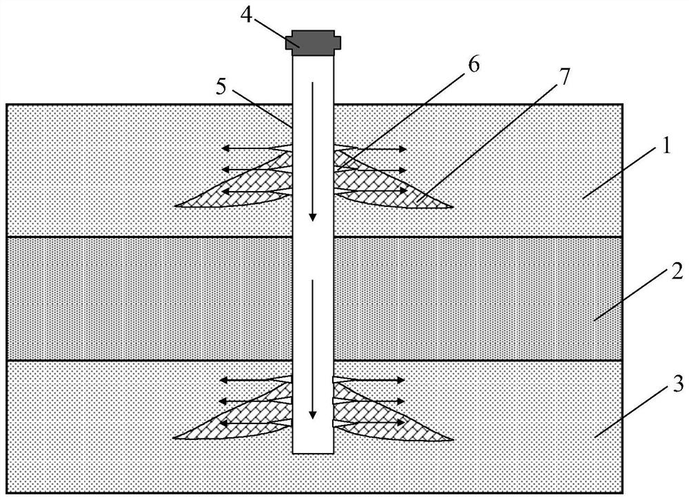
[0028] (1) According to the seismic, well logging and BSR geological data in the study area, the gas hydrate layer 2 with a thickness of 30 m, permeable cap layer 1 and permeable bottom cap layer 3 with a permeability of 20 mD is selected Hydrate reservoirs are mining objects, such as figure 1 shown;

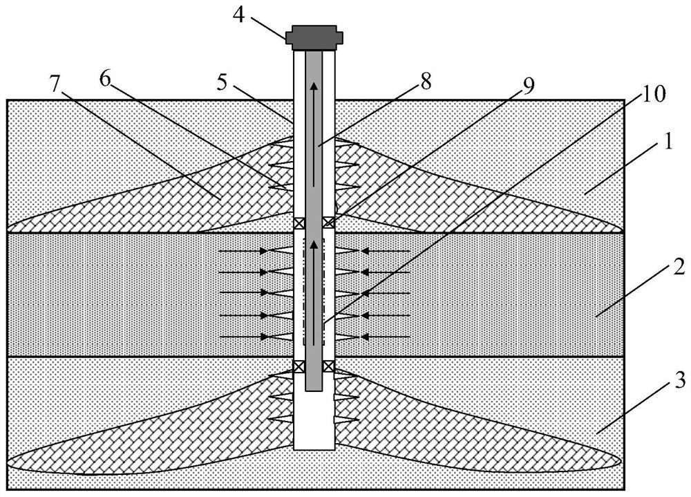
[0029] (2) if figure 1 As shown, a vertical well was drilled in the natural gas hydrate reservoir, and the completion layer was located 25m down from the interface between the hydrate layer 2 and the permeable bottom cap layer 3. The casing 5 in the permeable top cover layer 1 and the permeable bottom cover layer 3 are perforated 6 respectively, and the lowest perforation point in the permeable top cover layer 1 is located at the intersection of the hydrate layer 2 and the permeable top cover layer 1...


PUM


Abstract

The invention discloses a method for improving the recovery rate of natural gas hydrate reservoirs through artificial dense caprocks, which is mainly aimed at producing large water production volumes in production wells when exploiting natural gas hydrate reservoirs with permeable top caprocks and permeable bottom caprocks. , Small hydrate decomposition range, poor development effect, etc., by injecting cement slurry into the permeable caprock to form an artificial dense caprock, it can effectively prevent seawater from entering the hydrate layer in large quantities during decompression mining, and effectively increase the hydrate layer The production pressure difference between the production well and the production well, thereby increasing the rate of hydrate decomposition and recovery; the injected cement slurry has high strength after solidification, which can prevent geological disasters such as reservoir collapse caused by hydrate decomposition; The layer can also effectively prevent the migration of decomposed methane gas into the atmosphere through the permeable cap layer. The well structure of the invention is simple, easy to operate and highly economical, and can provide technical means for efficient exploitation of natural gas hydrate reservoirs with permeable cap rocks.

Description

technical field [0001] The invention relates to a method for improving the recovery rate of natural gas hydrate reservoirs through artificial dense cap layers, in particular, injecting cement slurry into permeable top cap layers and permeable bottom cap layers to form artificial dense cap layers to improve natural gas hydrate Tibetan recovery method. Background technique [0002] Gas hydrate is an ice-like compound formed by natural gas (usually methane) and water molecules under low temperature and high pressure conditions. It is mainly distributed in continental permafrost and seabed sediments with a water depth of more than 300 meters. Because of its high calorific value, clean and efficient, and huge resource potential, it is regarded as a strategic commanding height for future global energy development. Therefore, it is of great practical significance to develop high-efficiency recovery technologies for gas hydrate reservoirs. [0003] Among the global hydrate resourc...

Claims


Application Information

Patent Timeline
Patent Type & Authority Patents(China)
IPC IPC(8): E21B43/01E21B33/138
CPCE21B43/01E21B33/138E21B41/0099E21B43/16E21B33/146E21B43/11
Inventor 侯健赵二猛刘永革周康韦贝纪云开陆努白雅洁刘文斌
Owner CHINA UNIV OF PETROLEUM (EAST CHINA)
Learn More