
Intelligent well lid lock and intelligent well lid provided with same

An intelligent well and cover lock technology, applied in the application of locks, lock shells, building locks, etc., can solve the problem of the decline of the bearing capacity of the manhole cover, and achieve the effect of avoiding the decline of the bearing capacity, ensuring the structural strength, and improving the protection performance.

Pending Publication Date: 2019-08-23
ZHUHAI UNITECH POWER TECH CO LTD
View PDF0 Cites 3 Cited by
  • Summary
  • Abstract
  • Description
  • Claims
  • Application Information

AI Technical Summary

Problems solved by technology

The common form is external power supply or battery power supply, but not all occasions can provide external power supply. Battery power supply is affected by factors such as battery capacity, wear and tear, and the environment, which requires frequent maintenance and increases work intensity. In view of the above two power supply methods Due to limitations, it is necessary to find a reliable and convenient power supply method suitable for the application environment of the manhole cover lock, and the smart manhole cover lock body needs to be installed in the inner space of the manhole cover to prevent external damage, and the manhole cover is a load-bearing product, the smart manhole cover lock body Generally, the size is large. Setting a large area of ​​holes on the manhole cover for the installation of manhole cover locks will easily lead to a decrease in the bearing capacity of the manhole cover. Therefore, a special method is required to install smart manhole cover locks on the manhole cover. It can not only meet the convenience of power supply and operation, but also ensure the safety of the lock body and the manhole cover. load-bearing

Method used


Image

  • Intelligent well lid lock and intelligent well lid provided with same
  • Intelligent well lid lock and intelligent well lid provided with same
  • Intelligent well lid lock and intelligent well lid provided with same

Examples


Embodiment Construction

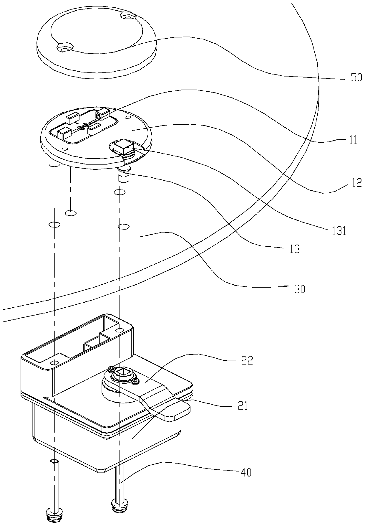
[0024] It should be noted that, in the case of no conflict, the embodiments in the present application and the features in the embodiments can be combined with each other. The present invention will be described in detail below with reference to the accompanying drawings and examples.

[0025] As recorded in the background technology, since the electronic locks of the smart manhole cover require functional requirements such as network management, remote control, information communication, and electronic control unlocking, the required energy consumption is also a problem that cannot be ignored. The common form is external power supply or battery power supply, but external power supply is not available in all occasions, and factors such as battery power, consumption, and environment cannot supply power for a long time, and frequent maintenance is required, which increases the work intensity.

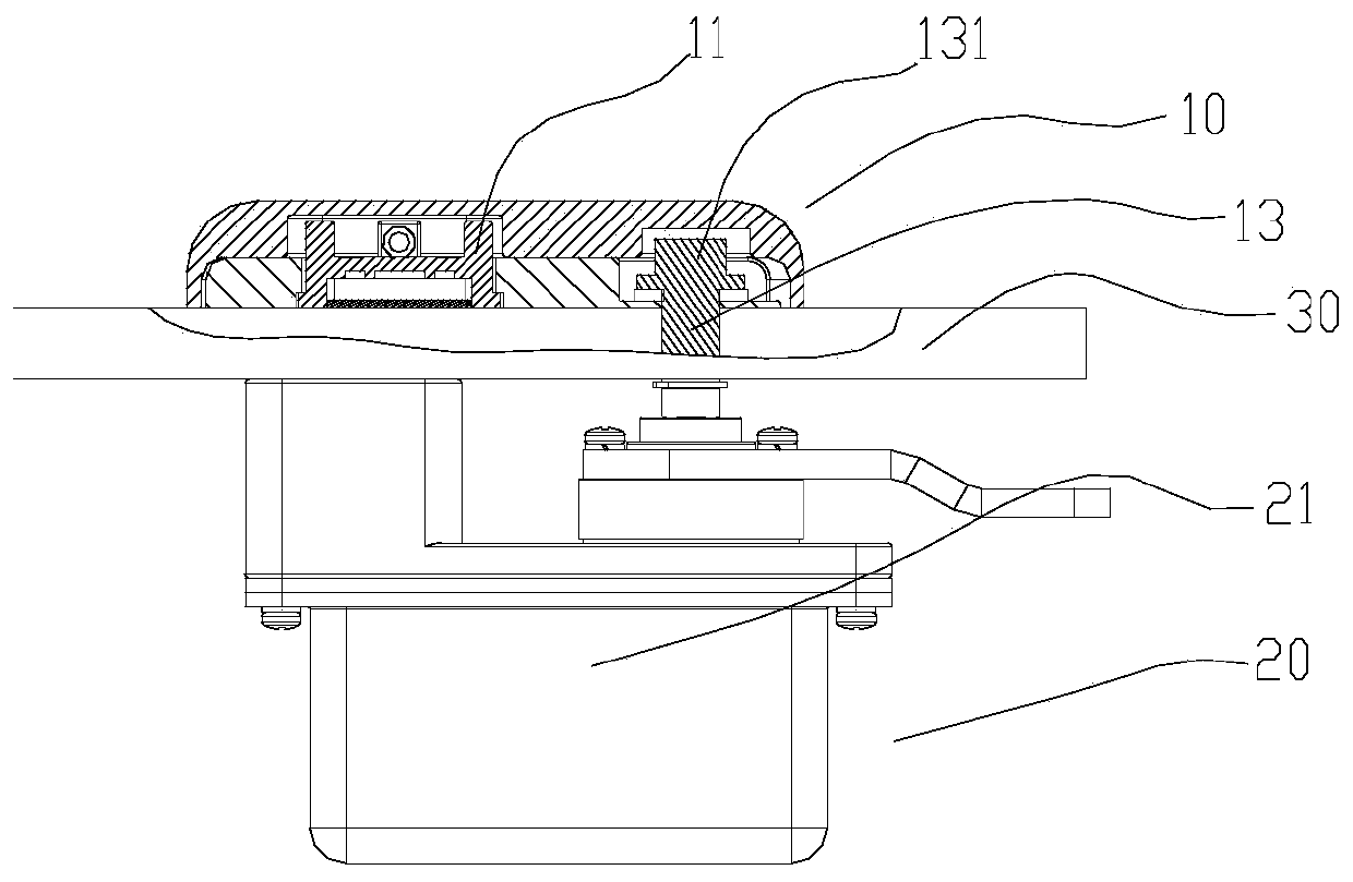
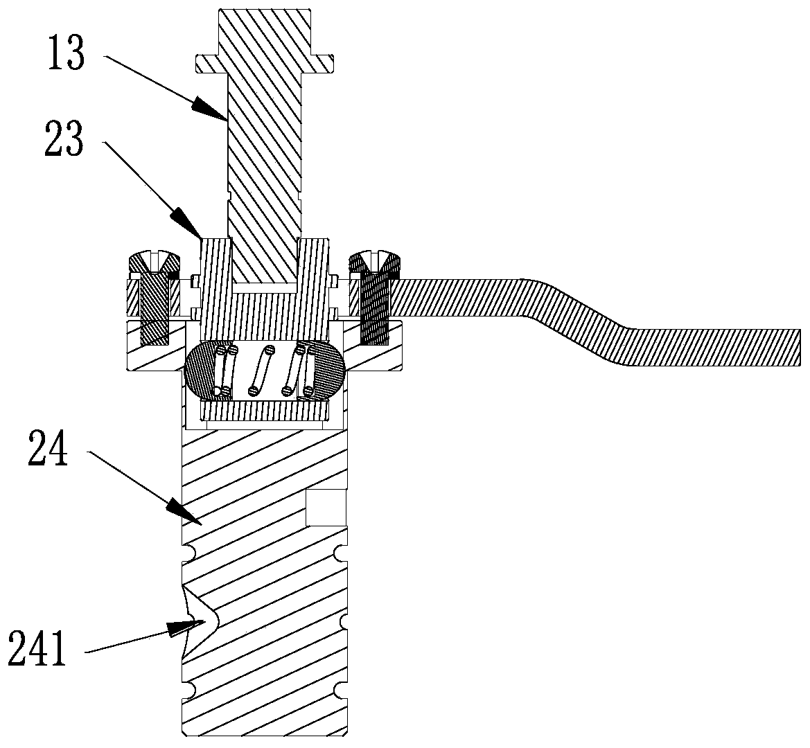
[0026] To solve the above problems, see Figure 1 to Figure 5 As shown, the present ...


PUM


Abstract

The invention provides an intelligent well lid lock and an intelligent well lid provided with the same. The intelligent well lid lock comprises a first lock body and a second lock body, wherein the first lock body is arranged on the top of a lower well lid; a power supply module is arranged inside the first lock body; and the second lock body is arranged on the back surface of the well lid for locking the well lid or unlocking the well lid. The intelligent well lid lock provided by the invention comprises the first lock body and the second lock body which are arranged on the top and the back surface of the well lid correspondingly, so that mounting of the intelligent well lid lock is convenient, protective performance is also improved, and the power supply module solves the problems that the external power supply is limited or a battery is frequently maintained, and the like in use of the intelligent well lid lock. Only a plurality of bolt through holes need to form in the well lid, sothat structural strength of the well lid is not affected, and therefore, the problem that bearing ability of the well lid is reduced as a result of large-area hole opening in the well lid in the prior art is avoided.

Description

technical field [0001] The invention relates to the technical field of intelligent well cover equipment, in particular to an intelligent well cover lock and an intelligent well cover with the same. Background technique [0002] With the gradual popularization and application of smart manhole covers, as one of the important functions of intelligent manhole cover management, the intelligent locking of manhole covers plays a very important role in the anti-theft and daily maintenance of the smart manhole cover system. At present, for the realization of the locking function of manhole covers, in addition to traditional mechanical locks, with the continuous development of technology, networked and intelligent electronic locks are gradually being used. [0003] Since electronic locks require functional requirements such as network management, remote control, information communication, and electronically controlled unlocking, the required energy consumption is also a problem that c...

Claims


Application Information

Patent Timeline
IPC IPC(8): E05B65/00E05B63/14E05B47/00E05B9/00E05B49/00
CPCE05B65/00E05B63/143E05B47/0001E05B9/002E05B49/002E05B2047/0057E05B2047/0026
Inventor 王岗王辉映刘仙赖鑫李迪
Owner ZHUHAI UNITECH POWER TECH CO LTD
Learn More