Maneuvering track front side view synthetic aperture radar tomography method

A technology of synthetic aperture radar and tomography, which is applied in the field of high-resolution three-dimensional imaging, can solve the problems of low imaging efficiency, achieve the effects of improving resolution, reducing redundant projection operations, and improving efficiency

Active Publication Date: 2019-08-20
XIDIAN UNIV
View PDF3 Cites 4 Cited by
  • Summary
  • Abstract
  • Description
  • Claims
  • Application Information

AI Technical Summary

Problems solved by technology

[0004] The purpose of the present invention is to address the deficiencies in the above-mentioned technologies, and propose a method for tomographic imaging of maneuvering trajectory front side-looking synthetic aperture radar, in order to solve the existing Low Imaging Efficiency in Front Side View 3D Tomography

Method used

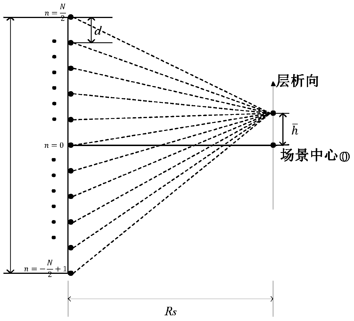

Image

  • Maneuvering track front side view synthetic aperture radar tomography method
  • Maneuvering track front side view synthetic aperture radar tomography method
  • Maneuvering track front side view synthetic aperture radar tomography method

Examples


Embodiment Construction

[0046] The technical solutions and effects of the present invention will be further described in detail below in conjunction with the accompanying drawings and specific embodiments.

[0047] refer to figure 1 , the implementation steps of the present invention are as follows:

[0048] Step 1. The linear array of the radar transmits and receives echo signals under the condition of uniform acceleration and linear motion

[0049] refer to figure 2 , the specific implementation of this step includes the following sub-steps:

[0050] Sub-step 1a, set a linear array radar to move in a straight line with uniform acceleration along the azimuth direction in the side-view imaging mode before level flight, and its motion equation is:

[0051]

[0052] Among them, X represents the azimuth position of the radar, v 0 Indicates the initial velocity of the radar, t indicates the full time, and a indicates the acceleration along the azimuth direction.

[0053] In sub-step 1b, it is ...


PUM


Abstract

The invention discloses a maneuvering track front side view synthetic aperture radar tomography method. The method comprises the following steps of in a maneuvering track front side view three-dimensional tomography process, uniformly dividing a route along an azimuth direction to obtain sub-apertures with a same length, and establishing a corresponding polar coordinate grid for each sub-aperture,wherein an angular domain division interval of each polar coordinate grid is determined by the sub-aperture length; then, projecting each sub-aperture data to the corresponding polar coordinate gridto form a sub-aperture image and acquiring a distance-azimuth two-dimensional imaging result through interpolation fusion; and finally, carrying out super-resolution sparse reconstruction on the datain each distance-azimuth unit along a chromatography direction through using a compressed sensing method to obtain a high-resolution three-dimensional tomography result. In the method of the invention, the lengths of the sub-apertures are the same, a problem of excessive sampling of an angular domain of the shorter sub-aperture and a large number of redundant projection operations during an entireimaging process when the lengths of the sub-apertures are not uniform are avoided, and imaging efficiency is increased.

Description

technical field [0001] The invention belongs to the technical field of digital signal processing, and relates to a tomographic imaging method suitable for a machine track synthetic aperture radar in a front side view mode, and can be used for high-resolution three-dimensional imaging of a uniformly accelerated motion platform. Background technique [0002] Synthetic Aperture Radar (SAR) can detect and image the observation area all-time, all-weather, and long-distance, and has a wide range of applications. Most of the SAR systems currently in use work in the side-view mode, relying on transmitting large time-broadband-bandwidth product signals to obtain high resolution in the range direction, and relying on platform movement to form a large synthetic aperture in the azimuth direction to obtain high resolution in the azimuth direction , only two-dimensional imaging can be performed. However, in navigation, autonomous landing, high-precision 3D terrain mapping and other occas...

Claims


Application Information

Patent Timeline
Patent Type & Authority Applications(China)
IPC IPC(8): G01S13/90
Inventor 刘峥赵晨冉磊谢荣
Owner XIDIAN UNIV
Why Eureka
Try Eureka