
Bridge detection device and method and bridge analysis system

A bridge detection and analysis system technology, applied in measurement devices, circuit devices, optical devices, etc., can solve the problems of insufficient bridge stability, consuming a lot of manpower and time, and impossible to achieve real-time monitoring, so as to be easy for users to understand , saving labor costs and avoiding damage to the strength of the bridge deck

Inactive Publication Date: 2019-08-20
无锡市高桥检测科技有限公司
View PDF16 Cites 1 Cited by
  • Summary
  • Abstract
  • Description
  • Claims
  • Application Information

AI Technical Summary

Problems solved by technology

[0002] At present, the commonly used method of bridge inspection on the market is to embed a deflection measuring scale on the bridge surface during bridge construction. During the inspection, it is necessary to manually fix the point for a long time to observe and record the scale of the measuring scale continuously, so the deflection detection requires a lot of time. Manpower and time, and it is impossible to monitor in real time
[0003] Bridge bearing offset does not require precise and uninterrupted detection. For the offset detection of bridges using basin bearings, manual inspections are carried out on the bridge deck every month to observe basin bearings on the bridge deck. The offset distance and record it, which may cause the support that has been offset too much to offset back again, and the inspection employee records the offset back data. The data is normal but the stability of the bridge is not enough

Method used


Image

  • Bridge detection device and method and bridge analysis system
  • Bridge detection device and method and bridge analysis system

Examples


Embodiment Construction

[0028] The following disclosure provides many different embodiments or examples for implementing different structures of the present invention. To simplify the disclosure of the present invention, components and arrangements of specific examples are described below. Of course, they are only examples and are not intended to limit the invention. Furthermore, the present disclosure may repeat reference numerals and / or reference letters in different instances, such repetition is for simplicity and clarity and does not in itself indicate a relationship between the various embodiments and / or arrangements discussed.

[0029] At present, the commonly used method of bridge inspection on the market is to embed a deflection measuring scale on the bridge surface during bridge construction. During the inspection, it is necessary to manually fix the point for a long time to observe and record the scale of the measuring scale continuously, so the deflection detection requires a lot of time. ...


PUM


Abstract

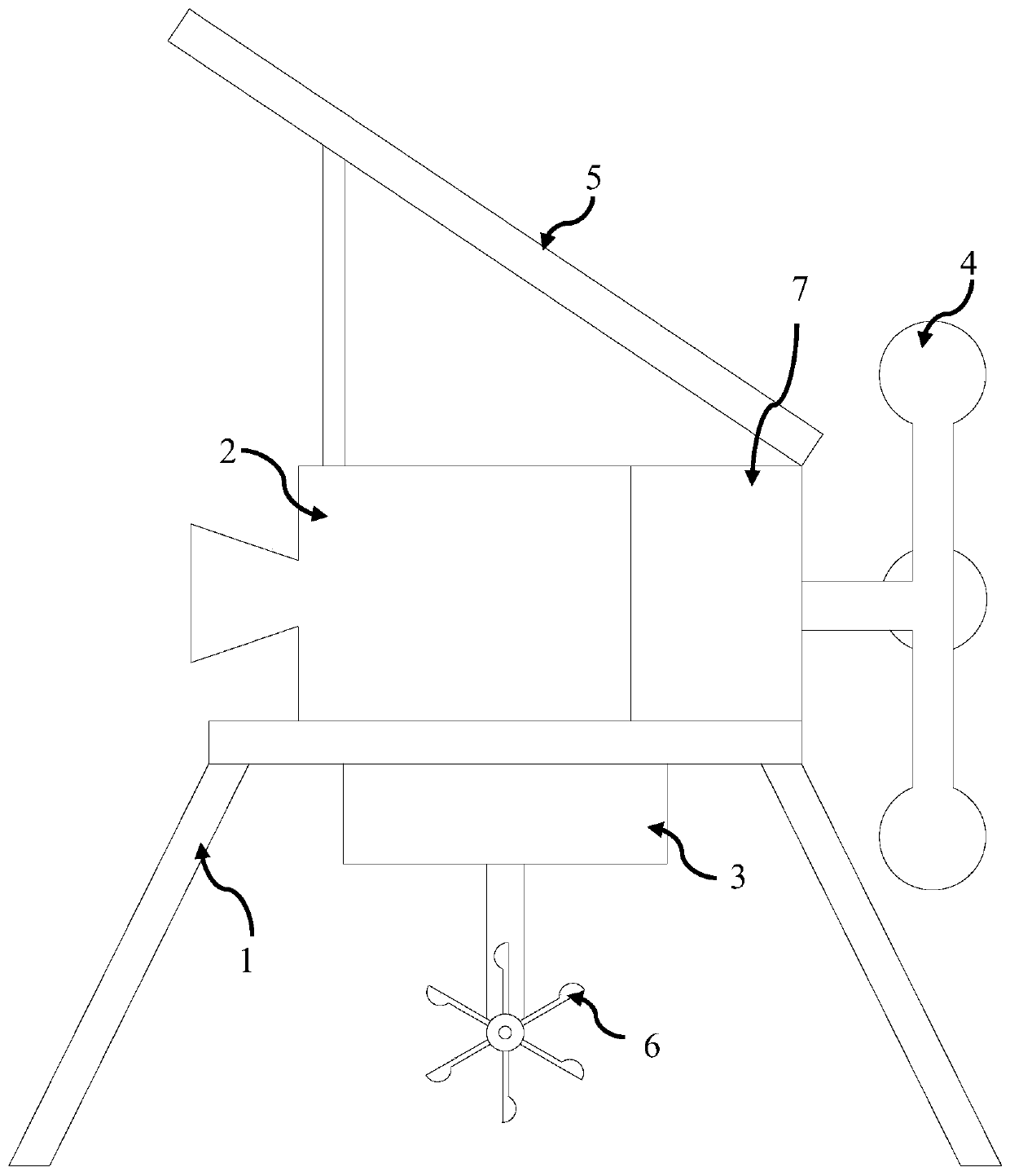
The invention discloses a bridge detection device relating to the technical field of bridge measurement. The bridge detection device comprises a flexibility detection device, a bridge bearer offset detection device and a communication module, the flexibility detection device comprises a flexibility detection camera, an infrared range finder and a support, the flexibility detection camera is placedon the support, the viewing side of the flexibility detection camera just faces the intermediate section of a bridge, the infrared range finder is mounted on the support and just faces the bridge, the support supports the flexibility detection camera so that the camera is stabilized over the water surface, a first lithium battery is arranged under the support, a first wind power generator is arranged in the side surface of the lithium battery, a hydroelectric power generator is arranged in the position where the support is sank to the water, and a first solar power generator is arranged in the top of the flexibility detection camera.

Description

technical field [0001] The invention relates to the technical field of bridge measurement, in particular to a bridge detection device, method and analysis system thereof. Background technique [0002] At present, the commonly used method of bridge inspection on the market is to embed a deflection measuring scale on the bridge surface during bridge construction. During the inspection, it is necessary to manually fix the point for a long time to observe and record the scale of the measuring scale continuously, so the deflection detection requires a lot of time. Manpower and time, and it is impossible to achieve real-time monitoring. [0003] Bridge bearing offset does not require precise and uninterrupted detection. For the offset detection of bridges using basin bearings, manual inspections are carried out on the bridge deck every month to observe basin bearings on the bridge deck. The offset distance and record it, which may cause the support that has been offset too much t...

Claims


Application Information

Patent Timeline
Patent Type & Authority Applications(China)
IPC IPC(8): G01M5/00G01B11/02F03D9/00F03D9/11F03D9/45F03B13/00F16M11/04F16M11/22H02J7/35
CPCF03B13/00F03D9/007F03D9/008F16M11/04F16M11/22F03D9/11F03D9/45G01B11/02G01M5/0008G01M5/0075H02J7/35Y02B10/30Y02E10/72Y02E10/728Y02E10/76Y02E70/30
Inventor 杨传国高亚伟刘邓博刘猛黄钰
Owner 无锡市高桥检测科技有限公司
Learn More